Control 24 Reference Guide52
5.1 Monitoring Output Connections
Figure 6 shows Control 24 audio output connections to a 5.1 monitoring system.
Important Reminder about Surround Formats
Keep in mind that the surround formats mentioned in this document require specific encoding and
decoding hardware or software in order to create multi-channel mixes in a specific surround format
(such as DTS, Dolby Digital, Dolby Surround (ProLogic) or others. See Pro Tools Reference Guide for
more information.
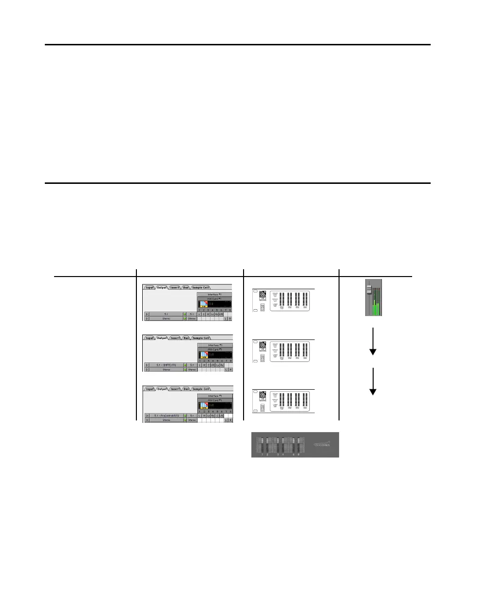
5.1 Track Layouts, Routing, and Metering
Pro Tools on-screen 5.1 meters are always mapped according to the Film standard L, C, R, Ls, Rs, LFE.
Output meters on Control 24 and Pro Tools Audio Interfaces, however, follow channel mapping in
I/O Setup.
Figure 6. Track Layout and metering of different 5.1 formats in Pro Tools
Audio Interface Meters
Track Layout in I/O Setup5.1 Format
L C R Ls Rs LFE
L R C LFE Ls Rs
L R Ls Rs C LFE
Film (Pro Tools Default)
SMPTE/ITU
DTS (Control
24 Default)
for Dolby Digital (AC3)
L C R Ls Rs LFE
L R C LFE Ls Rs
L R Ls Rs C LFE
Control
24 meters follow
audio interface meters
same
same
L C R Ls Rs LFE
Channel Meters
Control_24.book Page 52 Wednesday, January 17, 2001 2:51 AM