Chapter 7: Overview and Basics 59
The functionality is identical to that of your
computer’s keypad, including modifier-key
shortcuts. Throughout this guide, there are in-
structions for using the Numeric Keypad for all
of its various functions.
Channel Bar Display
The Channel Bar Display is an eight-character
display located above the scribble strips of chan-
nels 4 and 5. It typically displays the name of
the current track, function, or parameter infor-
mation (such as the name of an inserted effect),
often in conjunction with the scribble strips
(that might display the parameters of the in-
serted effect).
.
When Control 24 first comes on line, “Wel-
come!” appears in the Channel Bar Display. “Di-
alog!” appears whenever a dialog window in
Pro Tools appears on-screen.
The Channel Bar Display default is “L<>R Pan”
when a new session is created (and when the
Demo Session is opened for the first time). This
indicates that the default left-right panning
mode is active for the rotary data encoder on
each channel.
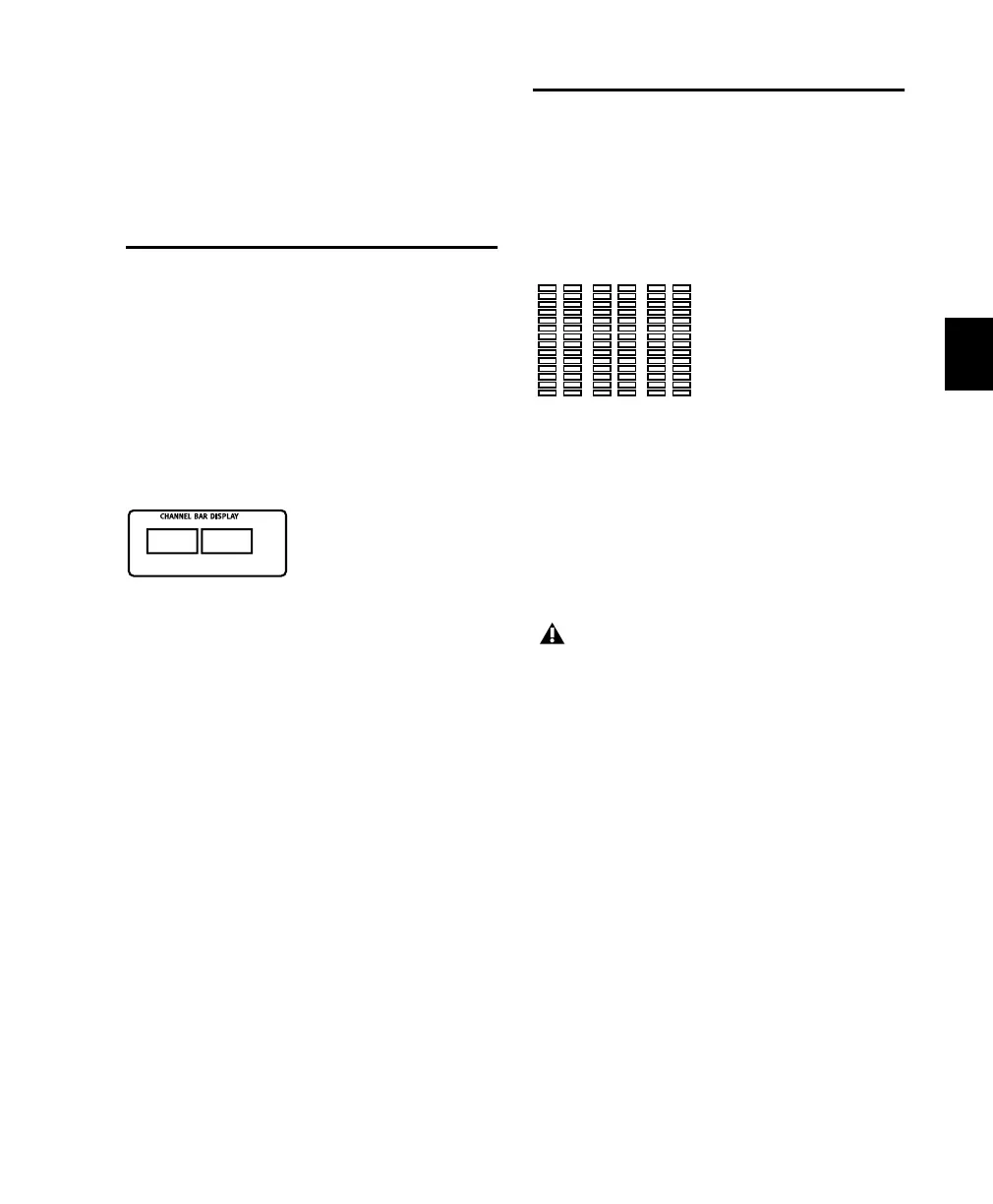
Level Meters
Along the top of Control 24 are 24 stereo, 14-
segment LED meters for global pre- or post-fader
level indication of individual channels. Mono
channels activate the left side of the meter pair
only.
.
There are six more meters to the left of the
counter display for master output levels. These
meters mimic the first six meters on the Digide-
sign 888 Audio Interface, and display multi-
channel metering when LCRS or 5.1 monitoring
modes are selected in the Control Room Moni-
tor section.
Control 24 meters follow Pro Tools Peak Indica-
tion preferences, and are identical in operation
to the meters on Digidesign Audio Interfaces.
To clear all clipped meters and held peaks:
■ Press the CLEAR PEAKS button to the left of
the channel meters.
Channel Bar Display, showing pan
PanL<>R
Output meters
Pro Tools on-screen 5.1 meters are always
mapped according to the Film standard
L, C, R, Ls, Rs, LFE. Output meters on
Control 24 and Pro Tools Audio Interfaces,
however, follow channel mapping in I/O
Setup. See
“5.1 Track Layouts, Routing, and
Metering” on page 52
.
Control_24.book Page 59 Wednesday, January 17, 2001 2:51 AM