Assembly and preparation
50 Instructions for use Perseus A500 SW 2.0n
Example of a permissible configuration:
P1= 400 mm * (4 kg + 5 kg) = 3600 mm*kg
(P1=15.7 in * (8.8 lbs + 11 lbs) = 310.9 in*lbs)
P2= 300 mm * (3 kg + 12 kg) = 4500 mm*kg
(P2= 11.8 in * (6.6 lbs + 26.5 lbs) = 390.6 in*lbs)
3600 mm*kg + 4500 mm*kg = 8100 mm*kg
(310.9 in*lbs + 390.6 in*lbs = 701.5 in*lbs)
8100 mm*kg < 8500 mm*kg
(701.5 in*lbs < 738 in*lbs)
If a combination of arms on one device side
exceeds the value of 8500 mm*kg (738 in*lbs),
tipping stability as per IEC 60601-1 is no longer
given. Check the tilting stability.
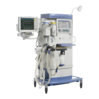
Mounting on the mounting rails
Depending on the position of the mounting rail, the
following weights are permissible:
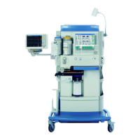
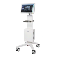
Special features of the ceiling-mounted
version
23537
Maximum
length
Arm weight Weight of the
attached com-
ponent
400 mm
(15.7 in)
4kg
(8.8 lbs)
5kg
(11 lbs)
300 mm
(11.8 in)
3kg
(6.6 lbs)
12 kg
(26.5 lbs)
Position Maximum weight
On the side of the work-
ing surface
10 kg
(22 lbs)
At the top on the rear of
the device
2.5 kg
(5.5 lbs)
WARNING
Risk of tipping over
If the weight of the mounted accessories
exceeds the permissible maximum weight,
the medical device may tip over.
Observe the maximum weight per arm.
WARNING
Risk of tipping over
If the weight of the accessories is unevenly
distributed about the device, the medical
device may tip over.
Distribute the weight evenly.
WARNING
Risk of tipping over
If the ceiling-mounted version has been
placed on the flexibility trolley or the service
cart, the information for fitting the
accessories still applies as for the ceiling-
mounted version.
– Pay attention to the maximum weight of
the accessories.
– Pay attention to the distribution of the
weight.