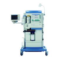
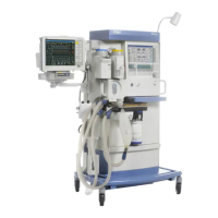
Instructions for use Perseus A500 SW 2.0n 63
Assembly and preparation
3 Connect the probe of the scavenging hose to
the terminal unit of the scavenging system.
As an option, the integrated anesthetic gas
receiving system can be operated in combination
with a control valve. Observe the assembly
instructions for the control valve.
Preparation for a day of operations / after reprocessing
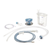
Assembling the breathing system
1 Check all parts for damage or wear:
– TurboVent 2 blower module
– APL valve
– Upper housing of the breathing system
– Lower housing of the breathing system
– Valve cages and valve plates
– Flow sensors
–Ports
– Incident flow meshes in the inspiratory limb
of the lower part of the breathing system
housing and in the expiratory port
– Seals and sealing rings
2 The following parts must be free from deposits:
– Incident flow meshes
– Non-return valves (red and blue)
If necessary, remove deposits on the valve
plates of the non-return valves with a soft cloth.
If the incident flow meshes are damaged,
contact DrägerService.
Installing the TurboVent 2 blower module
1 Insert the TurboVent 2 blower module (A) into
the breathing system mount.
10353
WARNING
Risk of insufficient anesthetic gas
concentrations
If the component connections of the
breathing system are not leak-tight enough,
ambient air may be added to the anesthetic
gas mixture.
Make sure that all components of the
breathing system are connected tightly.
10540