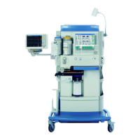
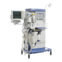
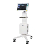
Assembly and preparation
60 Instructions for use Perseus A500 SW 2.0n
Connecting the gas cylinders on variants with
pin-index connections
Gas cylinder with pin-index connection:
Rear of device:
Before first use:
1 Insert the compressed gas hoses into the strain
relief (L) and screw the strain relief tightly into
place.
2 Connect the pressure measurement lines to
the connections (M).
3 Two fixing positions are possible for the gas
cylinder holder (K). Adjust the position of the
gas cylinder holder to the size of the gas
cylinder in use. Contact service personnel to do
this.
4 Remove the protection cap from the head of
the cylinder.
When changing gas cylinders:
5 Remove the old sealing washer (D).
6 Insert a new sealing washer (D) at the cylinder
holder (I).
7 Make sure that both pin-index pins (A) are
present below the gas inlet (B).
8 Align the gas cylinder (F) so that the pin-index
holes on the head of the cylinder (E) are
pointing towards the pin-index pins (A) on the
cylinder holder (I).
9 Insert the cylinder head (E) of the gas cylinder
(F) from below into the cylinder holder (I) of the
hanger yoke (J).
10 Allow the pin-index pins (A) to engage in the
pin-index holes.
11 Turn the handle (H) on the cylinder holder (I)
clockwise. The tip of the threaded retaining pin
will then be turned into the visible recess on the
cylinder head.
Make sure that the gas cylinder (F) is
suspended vertically.
12 Tighten the handle (H) on the cylinder holder
(I).
13 Secure the gas cylinders (F) with hook-and-
loop straps (K).
If required, the gas cylinder valve (C) can be
opened with the supplied wrench (G).
2042120415