7 Pin and Terminal Assignments of UA 4xx E
7.1 Terminal diagram
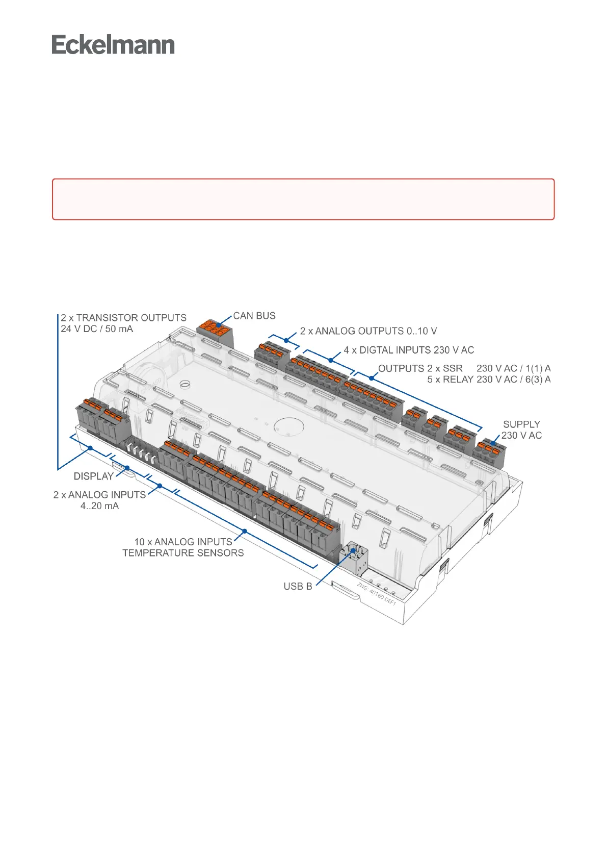
Connection diagram of the case controller with terminal designation, shown here in the UA 410 E AC complete
design.
The case controller UA 4xx E is available in UA 410 E AC / UA 400 E CC / UA 401 E CC, see details in chapter
Versions.
ConnectiondiagramUA410AC-completedesign
One zode controller and two zone controller, with analog in and outputs, RTC and battery
Warning about dangerous electrical voltage!Inordertoguaranteereversepolarityprotection,only
coded mating connectors may be used on the control component connections.