•
•
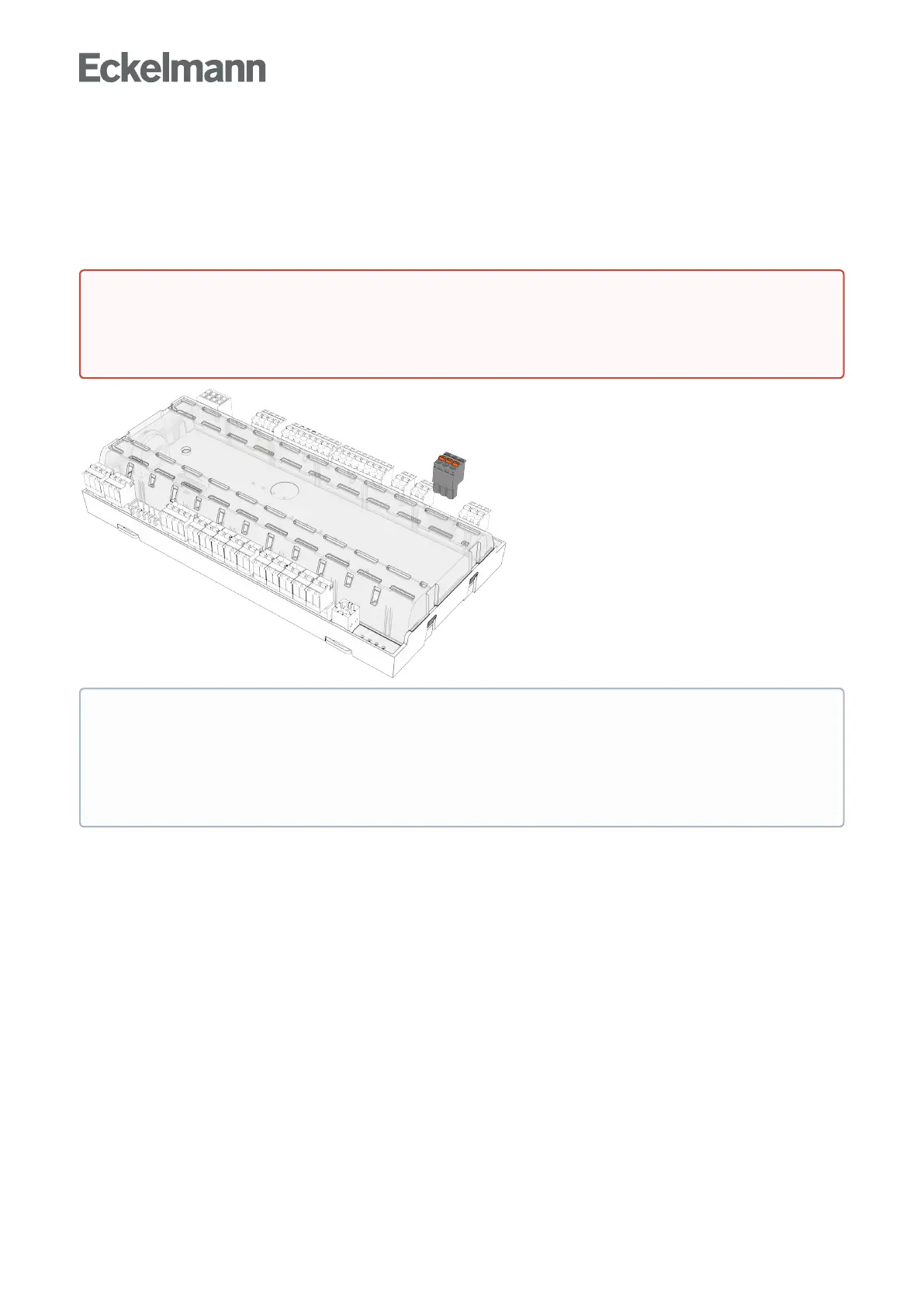
5.9 Alarm relay
Only UA 400 E CC / UA 410 E AC
The case controller has a floating relay output for alarms (relay 1, terminals 15/16/18); for details, see chapter
Terminalassignmentofthe230VACrelayoutputs). If an alarm is signalled by the case controller, the relay
output is activated (relay drops out, see chapter Function of the relay and transistor outputs.
5.10 Fan control with case and coldroom controllers
5.10.1 Fan control on multidecks - controller type UA 121 E
Thefancontinuesrunningduringcoolinganddefrosting.Withexternaltogglingofsetpointsfromset1toset1–
butnotviceversa–thefansstopforanadjustabletime(parameterBlindOnTime).Thisisnecessaryto
ensuretroublefreeclosingofthenightblind(e.g.onLightOFF).
The fan relay is the inverted type,
when the controller turns on the fan, then the relay contact (73/73) is opened;
when the controller turns off the fan then the relay contact (73/73) is closed.
5.10.2 Fan control - controller type UA 131 E
The fan is switched on during refrigeration. Fan behaviour during defrosting can be adjusted (switch off /
continuousoperation).ThefancontrollerusesthedefrostsensorsR1.1andR1.2aswellasarelayfor
DANGER
Warning about dangerous electrical voltage! Danger of electric shock! BEFORE connecting and
disconnecting, it must be checked that no voltage is presentatthe230VACrelayoutputs!Low
voltage and safety extra-low voltage must not be applied together at the relay outputs!
ATTENTION
In standalone operation, the relay output must be used e.g. to control an alarm device in order to
ensure that an alarm is triggered. If the case controller is operated in the E*LDS system, the relay
output is usually not required, as the system centre in CAN bus mode takes over the task of alarm
signalling.