7.13 Wiring of the master-slave function for defrost synchronisation
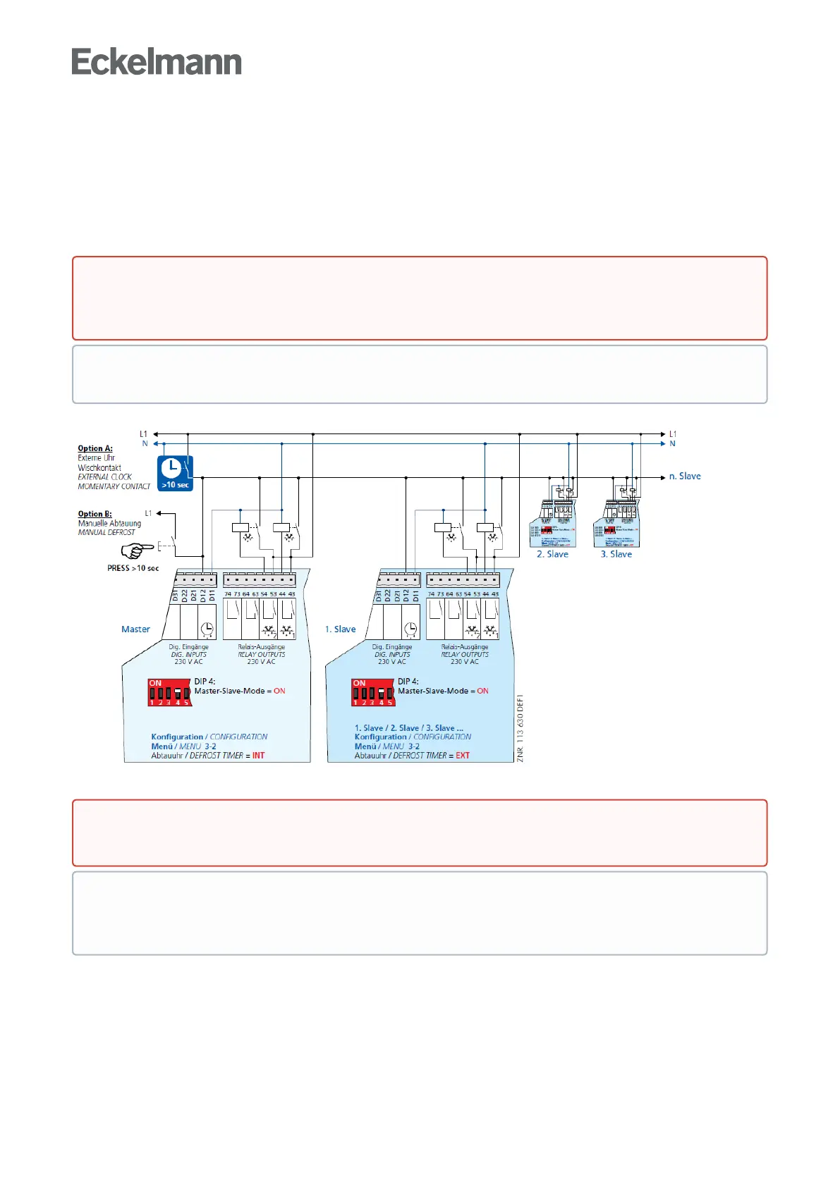
For defrost synchronisation the auxiliary contactors of the master defrost relay are switched in parallel and
thenroutedasa230Vsignaltotheslave’sexternaldefrostinput(terminalsD11/D12).Theauxiliarycontactors
oftheslavecontrollerarealsoconnectedinparallelandconductedbackasa230Vleveltotheexternal
defrostinputofthemaster.Thisenablesthesoftwaretodeterminewhetherdefrostingisstilltakingplacein
both case controllers.
Warning - hazardous electrical voltage!
Danger of electric shock! BEFORE and AFTER connection it must checked that the 230 V AC digital
inputs are off load!
The description and operating instructions for the master-slave mode are contained in chapter Master/
slavemode–defrostsynchronisationviawiring.
Danger of short circuit! When wiring master and slave case/coldroom controllers, make sure that
power supply is made with only one phase (e.g. only through L1, see illustration)!
Defrosting is terminated by the software not later than when the set safe defrost time expires. The
external clock must be wired as a passing contact as it only provides the start signal for the defrosting.
The shutdown is entirely managed by the participating controllers according to their safe defrost time.