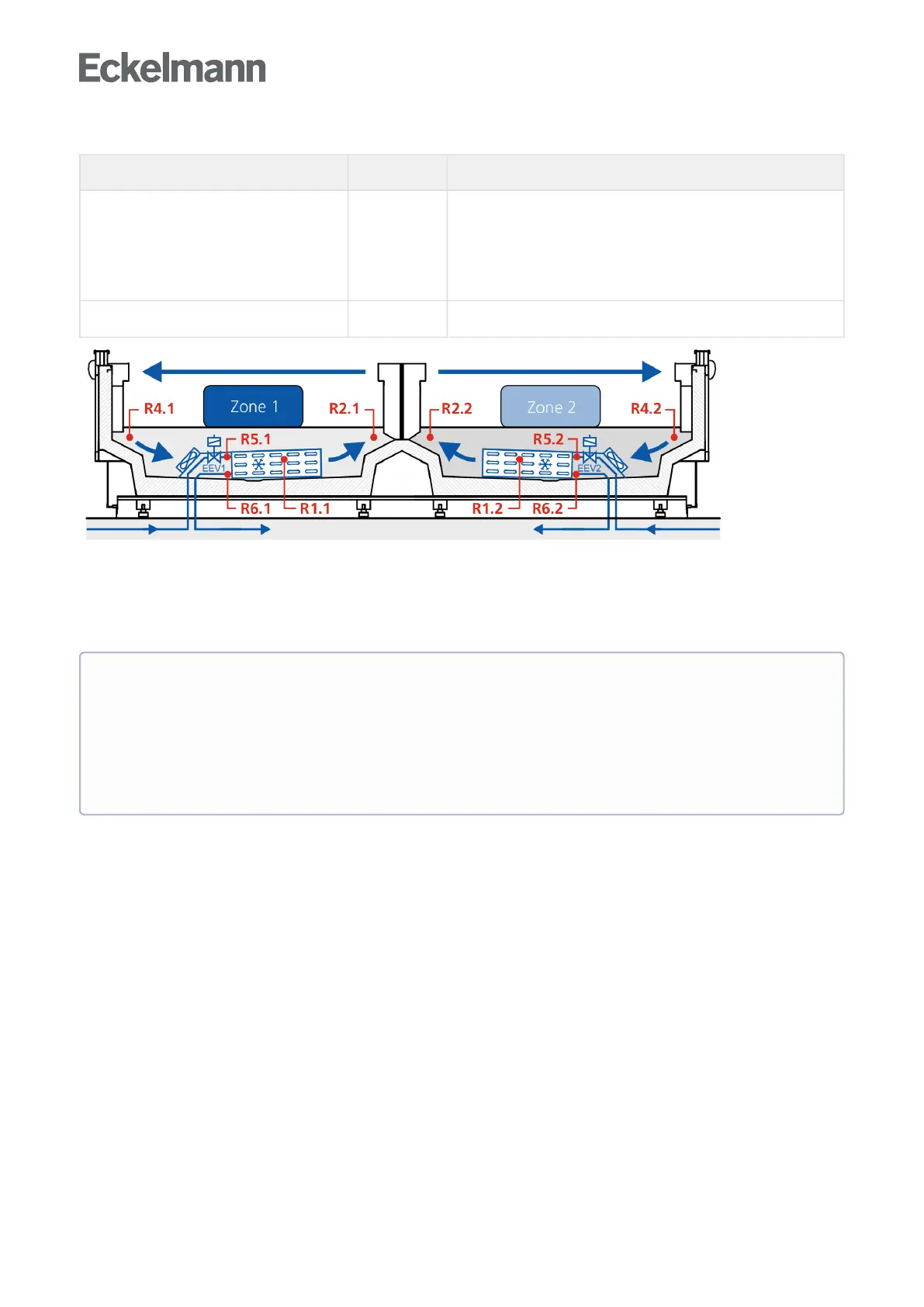
Explanation for the sensor designation
Legend: Ry.x
y = type of the sensor 1
2
4
5
6
Defrost sensor
Supply air sensor
Return air sensor / room air sensor / refrigerant temperature sensor
(UK 100 E)
Evaporator inlet sensor
Evaporator outlet sensor
x = case 1/2 Zone 1 / Zone 2
Error message in the event of sensor fault
An alarm (sensor fault) is always triggered if necessary sensors are not attached. If optional sensors are not
attached, this alarm only occurs if these sensors have been incorporated in a sensor scan. A sensor scan is
started via menu 6-1 (see chapter Menu Structure).
5.6 Description of controller functions
The sections that follow describes the various functions of the case controller for control of refrigeration
pointsequippedwithanelectronicexpansionvalve.Theavailabilityofcertaincontrollerfunctionsisgoverned
bywhichcontrollertypeissetonDIPSwitchS3(seeSectionSetting the controller type and other functions).
ATTENTION
TheevaporatorinletsensorsR5.1andR5.2areoptional, if the case controller on the CAN bus is
operated with a pack controller. In standalone operation using evaporator inlet sensors, R5.1 and
R5.2 are necessary sensors, see chapter Standalone operation using evaporator inlet sensors! These
must be connected and integrated using sensor scan to prevent any error message! In the case of
optional sensors that are not included in a sensor scan, no actual values are archived in the system
centre / store computer.