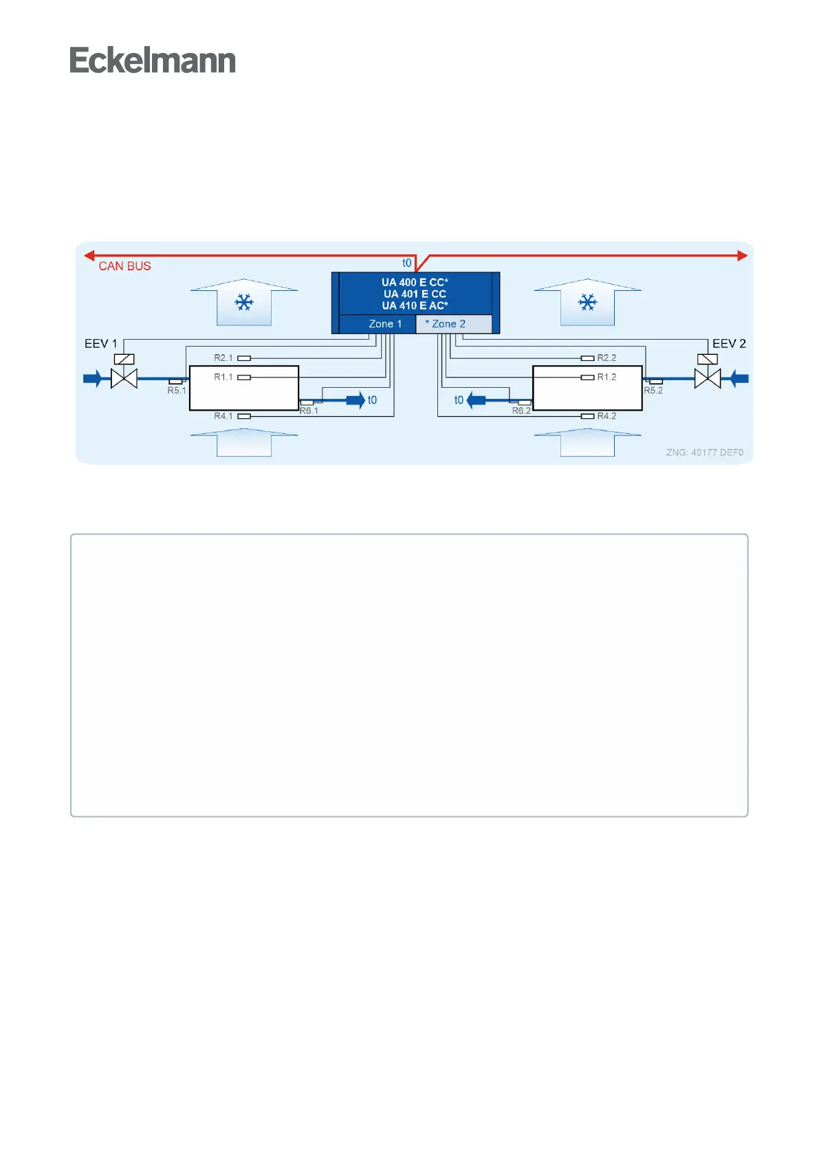
5.3 CAN bus mode
The controller is integrated in the CAN bus in this operating mode. The remote control via a terminal is
generally performed via the system centre, which also takes care of the alarm management. In addition, the
suction gas temperature t
0
of the pack controller belonging to the refrigeration circuit via the CAN bus is used to
determine superheat.
For this operating mode, a correction offset fro the pressure losses in the suction line must be determined for
each refrigeration point and set to "xx" using the parameter Korroff. t
0
(menu 6-3). If the parameter Korroff. t
0
is
set to "--", the controller is then in Standalone operation!
•
•
ATTENTION
Compressor damage! Danger due to liquid refrigerant on the suction side of the compressor!
Operatingmodet
0
via CAN bus (menu 6-2-6)
The evaporator inlet sensors R5.1 and R5.2 should also be connected in the t
0
via CAN
busoperatingmode.Thisresultsinimprovedemergencyrunningcharacteristicsintheeventof
failure of the CAN bus transmission. In standalone operation (without local pressure transmitter),
the sensors, R5.1 and R5.2 must be connected; see chapter Standalone operation using
evaporator inlet sensors!
Operatingmodet
0
local Z1 / Z2 (menu 6-2-6)
In the case of evaporators with high cooling capacity which require high control dynamics, the
superheat control should be realised via a local pressure transmitter (only UA 410 E AC); see
chapters Standalone operation using activated local pressure transmitter and Emergency Op..
Superheat control only via sensors R5.1 and R5.2 is not recommended, as there is a risk of
evaporator flooding due to the slow response behaviour!