•
•
5.8.4 Master/slavemode–defrostsynchronisationviaCANbus
All controller types from version >= V2.00, except UK 100 E or KR 160 E
Requirements
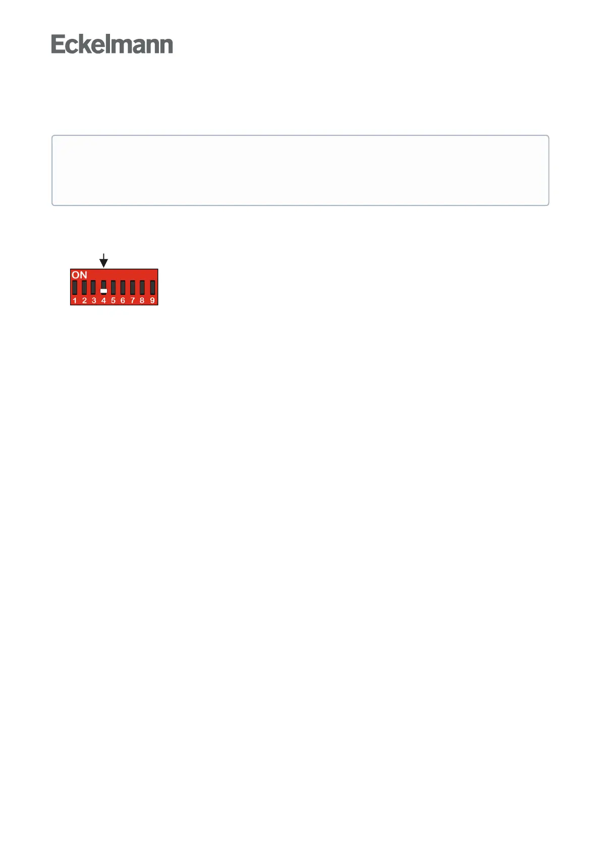
Setting of the DIP switch S3, coding switch 4 must be set to OFF;fordetails,seechapterSetting the
controller type and other functions.
Software settings, see below for details.
Function Description
The master/slave mode is used for refrigerated cases, for which the operation of multiple evaporators can result
inreciprocalicingoftheevaporatorswithoutfurtherprotectivemeasures.Thisproblemispreventedduetothe
defrost synchronisation in master/slave mode. All refrigerated cases and case zones defrost simultaneously
and then switch to cooling together. For this type of master-slave mode, multiple involved controllers are
synchronised via the CAN bus. The master/slave defrost via CAN bus covers the following functions: Following
a joint defrost, a group of controllers only switches back to cooling when all the controllers have completed their
respective defrost. Thus the transition from defrost to cooling is synchronised for all the case controllers in a
defrost group. The case controllers in a defrost group are divided into a defrost master and the defrost slaves.
The defrost master sets the defrost start, and at the end of the process, enables cooling again. All the other
defrost participants (when existing) are called defrost slaves and follow the instructions of the defrost master.
Several independent defrost groups can be realised, i.e. a number of defrost masters who each administer an
arbitrary number of defrost slaves. In addition to the defrost groups, further controllers entering defrost within
thesystemcanexistindependentlyofthegroups.Thesizeofthedefrostgroupsaswellasthenumberof
defrost groups is only limited by the maximum number of nodes in the E*LDS system.
Execution or sequence of the master / slave defrost via the CAN bus
A defrost is initiated at the master. From this point in time, all the slaves enter a defrost. As long as any of the
participants(slavesorthemaster)isstillindefrost,noneofthecontrollersinvolvedwillswitchtocooling.
f the defrost end temperature has been reached at one of the controllers, this controller sets its own defrost
relaytoOFF,butremainsinthedefroststateanddoesnotchangetothecoolingstate.
When all controllers involved have reached the end of the defrost cycle (whether via the safety time or via the
defrost termination temperature), they all return to the "cooling" state together.
The safety time set at the master and any waiting or dripping time set at the master is also used by the slaves.
ATTENTION
Damage to the system and stock loss!Whenusingthisfunction,itmustbeensuredthatincorrect
parametrisation does not result in simultaneous defrost and cooling of the synchronised refrigeration
points.