•
•
•
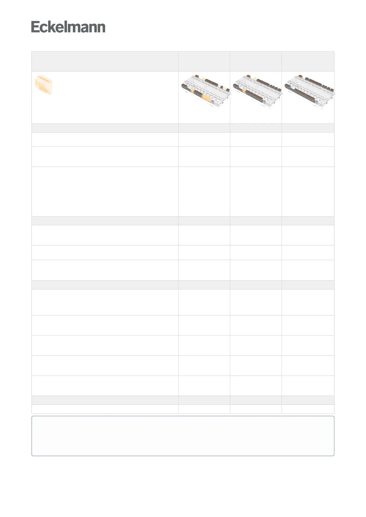
Mounting variants UA 401 E CC UA 400 E CC
UA 410 E AC
(complete design)
= terminals not mounted
For details, see chapter Terminal diagram.
Interfaces
CANbus,communicationintheE•LDSsystem
• • •
DISPLAY - Connection for BT 300 x operator interface and up to
four BT 30 temperature displays
• • •
USB
For direct parametrisation of the case controller via
LDSWin or
For carrying out a firmware update of the case controller
or
For parametrisation of system components via CAN bus
using LDSWin
• • •
Inputs
Digital inputs
230 V AC, floating output
4 4 4
Analogue inputs
for temperature sensors (2-wire, NTC)
5 10 10
Analogue inputs 4..20 mA
, e.g. for the connection of pressure transmitters or a humidity
sensor
- - 2
Outputs
Semiconductor relay (SSR) 230 V AC / 1 A (SSR = Solid State
Relay)
normally open contact, for controlling electronic expansion valves)
1 2 2
2 x transistor outputs
24 V DC / 50 mA (Light control, Frame and pane heater)
2 2 2
Relay outputs
230 V AC / 6 A (normally open contact)
4 4 4
Relay output (Alarm relay)
230 V AC / 6 A (changeover contact)
- 1 1
Analogue outputs 0..10 V DC
e.g. for Control of continuous motor expansion valves
- - 2
Real-time clock
RTC, with power reserve, lithium cell (battery) - - •
Details about the distinguishing features of the controllers are explained in chapter Versions.The
application areas of the case controller are described in more detail in chapter Controller types. The
connection and terminal assignment are described in chapter Pin and Terminal Assignments of UA 4xx
E.