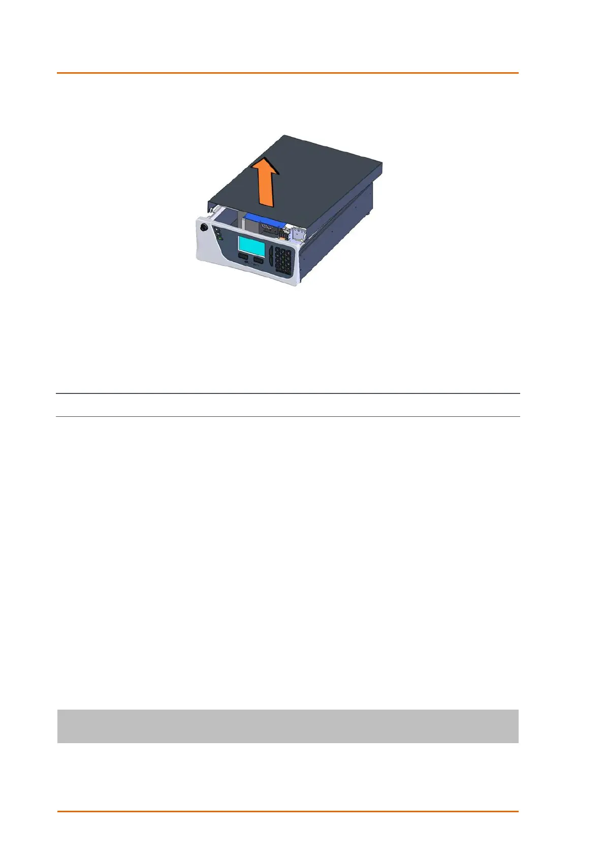
4. Refer to Figure 16. To completely remove the lid, slide the lid backwards until the rollers line up
with the gaps in the track and lift the lid upwards to remove from the instrument.
Figure 16 – Opening the Instrument – 4
5. Check that all pneumatic and electrical connectors are connected. If not, reconnect.
6. Check for any visible and obvious damage. If damage exists contact your supplier and follow the
instructions in claims for Damaged Shipments and Shipping Discrepancies at the front of this
manual.
2.2 Installation Notes
When installing the instrument, the following points must be taken into account:
The instrument should be placed in an environment with minimal dust, moisture and variation in
temperature (refer to Section 2.4 and 2.5 for specific approval set-up).
For best results the instrument should be located in a temperature and humidity controlled
environment (air conditioned shelter). An enclosure temperature of 25 - 27 °C is optimum.
Whether in a rack or placed on a bench, the instrument should not have anything placed on top of
it or touching the case.
Instruments should be sited with easy access to the front panel (instrument screen/USB memory
stick) and to the back panel (communication ports/pneumatic connections).
It is recommended that the sample line be as short as possible and/or a heated manifold be used
for sampling (minimising moisture condensation in the sample).
Do not pressurise the sample line under any circumstances. Sample should be drawn through the
instrument under atmospheric pressure. This should be achieved by either using the internal pump
option (if installed) or an external vacuum pump connected to the exhaust port of the instrument.
When supplying span gas, ensure the flow is approximately 1 slpm and excess is sufficiently vented.
The chassis fan on the rear panel should be kept free of any obstructions.