where:
T
Factor to convert selected time base to seconds
N
Number of pulses per flow unit, as configured in the receiving device
The resulting Frequency Factor must be within the range of the Frequency Output :
• If Frequency Factor is less than1 Hz, reconfigure the receiving device for a higher pulses/unit setting.
Configure Frequency=Flow
You want the Frequency Output to report all flow rates up to 2000 kg/min.
The frequency receiving device is configured for 10 pulses/kg.
Solution:
FrequencyFactor
RateFactor
T
× N
FrequencyFactor
2000
60
× 10
FrequencyFactor = 333.33
Set parameters as follows:
• Rate Factor: 2000
• Frequency Factor: 333.33
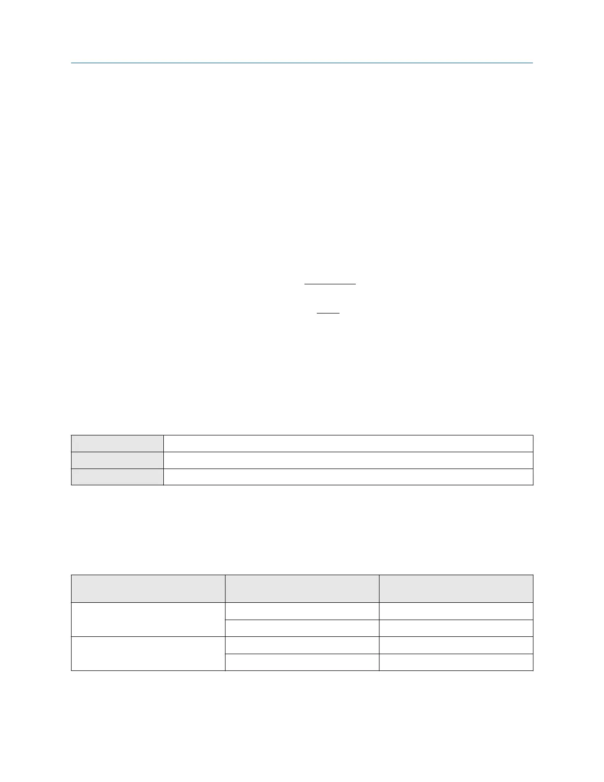
8.4.3 Configure Frequency Output Direction
Display
Menu > Configuration > Inputs/Outputs > Channel x > I/O Settings > Direction
ProLink III Device Tools > Configuration > I/O > Outputs > Frequency Output x > Direction
Field Communicator Configure > Manual Setup > Inputs/Outputs > Channel x > Frequency Output x > FOxSettings
Frequency Output Direction controls how conditions of forward flow and reverse flow affect the flow rates
reported by the Frequency Output.
Actual flow direction interacts with Sensor Flow Direction Arrow to determine the flow direction that the
transmitter uses in processing. See the following table.
Table 8-2: Interaction between actual flow direction and Sensor Flow Direction Arrow
Actual flow direction Setting of Sensor Flow Direction
Arrow
Flow direction sent to outputs and
totalizers
Forward (same direction as Flow arrow
on sensor)
With Arrow Forward
Against Arrow Reverse
Reverse (opposite from Flow arrow on
sensor)
With Arrow Reverse
Against Arrow Forward
Integrate the meter with the control system Configuration and Use Manual
March 2019 MMI-20025166
152 Micro Motion Model 5700 Transmitters with Configurable Outputs

 Loading...


