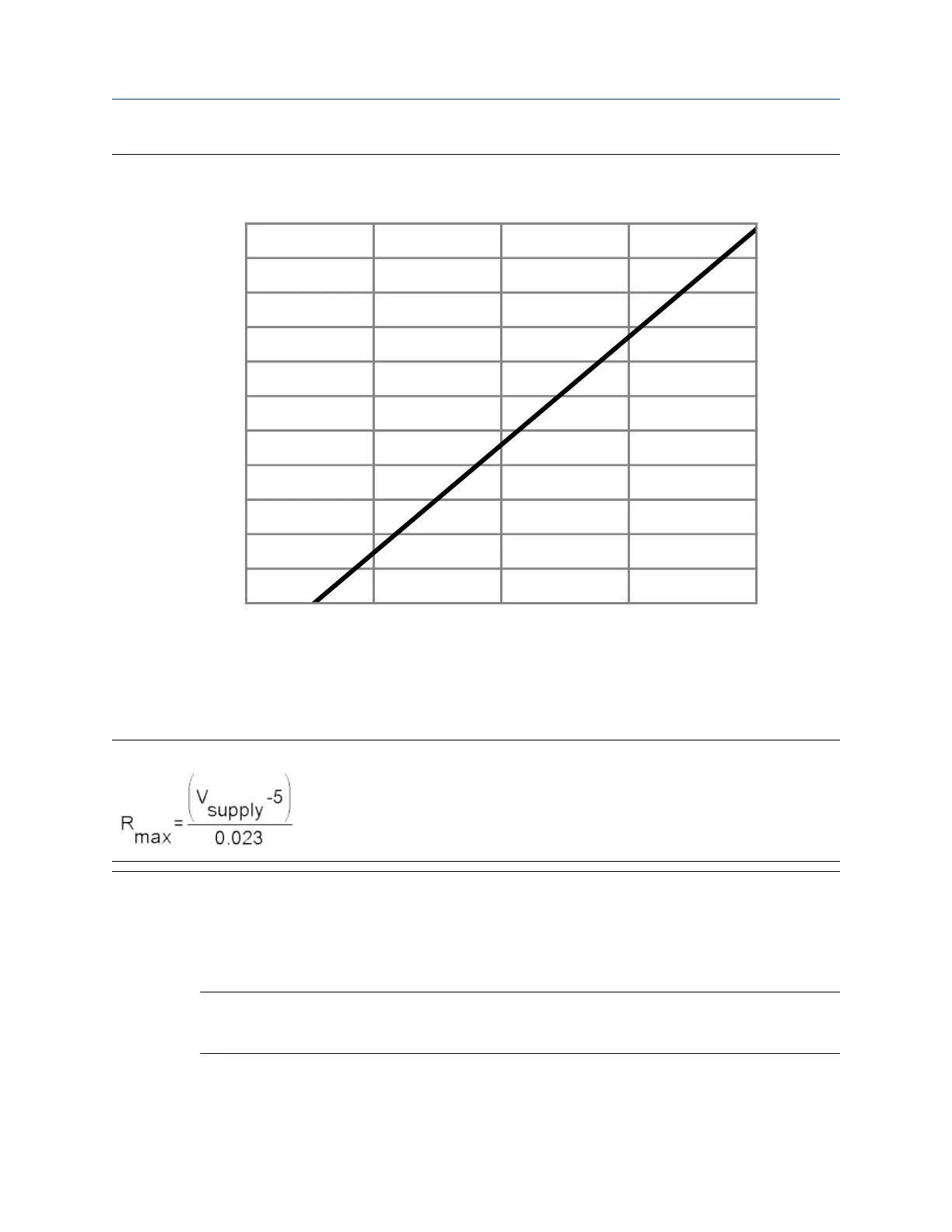
Figure B-7: Externally powered mA output: maximum loop resistance
0
100
200
300
400
500
600
700
800
900
1000
1100
0 7.5 15.0 22.5 30.0
B
A
A. Maximum resistance (Ω)
B. External supply voltage (V)
Note
3. To connect to a point in the local HART loop:
a) Attach the leads from the signal converter to any point in the loop, ensuring that the leads are
across the resistor.
b) Add resistance as necessary to achieve at least one volt across the connection points.
Important
HART/Bell 202 connections require a voltage drop of 1 VDC. To achieve this, add resistance of
250–600 Ω to the connection.
Configuration and Use Manual Using ProLink III with the transmitter
MMI-20025166 March 2019
Configuration and Use Manual 327

 Loading...


