EasyManuals Logo

Emerson Micro Motion 5700 Configuration And Use Manual

Emerson Micro Motion 5700
356 pages
To Next Page IconTo Next Page
To Previous Page IconTo Previous Page
Page #323 background imageLoading...
Page #323 background image
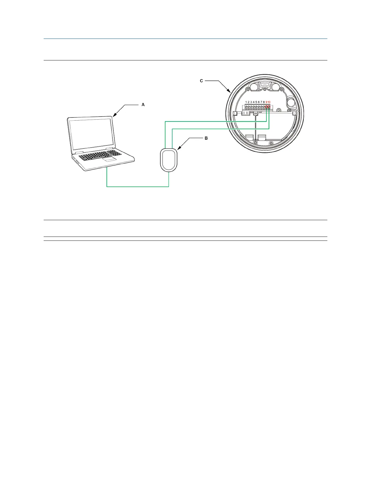
Figure B-4: Connection to transmitter terminals
A. PC
B. Signal converter
C. Transmitter, with wiring compartment and power supply compartment opened
Note
This figure shows a serial port connection. USB connections are also supported.
3. To connect over the RS-485 network:
a) Attach the leads from the signal converter to any point on the network.
b) Add resistance as necessary to achieve at least one volt across the connection points.
Configuration and Use Manual Using ProLink III with the transmitter
MMI-20025166 March 2019
Configuration and Use Manual 323

Table of Contents

Other manuals for Emerson Micro Motion 5700

Questions and Answers:

Question and Answer IconNeed help?

Do you have a question about the Emerson Micro Motion 5700 and is the answer not in the manual?

Emerson Micro Motion 5700 Specifications

General IconGeneral
Model5700
TypeTransmitter
Measurement PrincipleCoriolis
EnclosureAluminum or stainless steel
Output Signals4-20 mA
Communication ProtocolsHART
DisplayOptional LCD
Operating/Ambient Temperature Range-40 to 60 °C (-40 to 140 °F)
Materials of ConstructionStainless steel
Enclosure RatingIP67
Hazardous Area ApprovalsATEX, IECEx
DiagnosticsComprehensive diagnostics available

Related product manuals