Maintenance 3. Controller Structure
RC620 Rev.8 131
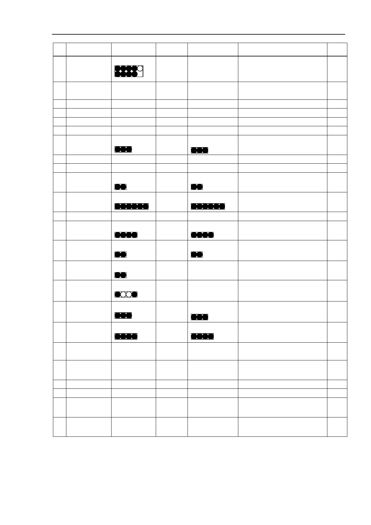
No.
Connection
Connection Note
21
CPU
(High speed)
9
8 4,10 DMB, FPB *3
22
CPU
6,16,4
10 10 PCI-BPB *3
20 4,4,4,4,2,2
27 DMB
3
3
3
FAN1
29 DMB 40 36,4 40 FPB
30 DMB
2
2
2
Battery
31 DMB
6
6
6
FPB
33 DMB
4
4
4
ADMB *2
34 DMB
2
2
2
ADMB *2
35 DMB
2
2
−
Regenerative thermostat *1
36
Regenerative
Board
4
2
−
Regenerative Resistance *1
37 DMB
3
3
3
FAN2
38 PCI-BPB
4
4
4
FPB
39 ADMB
100 50<F>,
100 DMB *2
40
M/C power
50
32
4,4,4,4
DMB/ADMB *6
43 ADMB
50
16 4,4,4,4,2,2
Additional Axes
M/C power connector (M1-M4)
*7
44 ADMB
50
8 4,4,2
Additional Axes
M/C power connector (M1, M2)
*8
<M>: Molding cable
*1 : When connect to regeneration module
*2 : When use Axis #5 to Axis #8
*3 : When connect to CPU board (High Speed type)
*4 : When connect to RAID option
*5 : When connect to DVD drive
*6 : When connect to Six axis manipulator
*7 : When connect to additional axes with M/C SIGNAL-2
*8 : When connect to additional axes with M/C POWER-2