Maintenance 6. Maintenance Parts Replacement Procedures
RC620 Rev.8 159
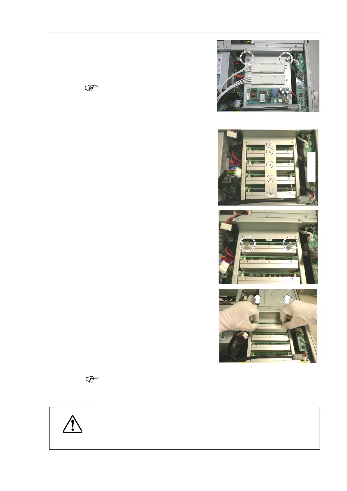
Remove 2 finger screws and the plate on
which the switching power supply is
mounted.
Use these finger screws to pull
out the
Remove 5 finger screws and motor
driver
mounting bracket.
Motor Driver
1: Axis #1
2: Axis #2
3: Axis #3
4: Axis #4
2 finger screws removed in the step
(5) in the screw holes on the heatsink of
motor driver.
Pinch 2 finger screws and apply equal
force to the right and left sides to pull
out the motor driver.
When the G10 series / G20 series manipulator is connected, cable and connector are
connected to the motor driver Axis #1 and Axis #2.
When pulling out the motor driver, be careful not to catch the connectors between the
chassis.
CAUTION
Be careful not to cut your finger.
The joint of motor driver connectors can be very tight. For that, if you pull the
motor driver forcibly, the connector may be pulled out suddenly and you may get
a cut on your finger with the motor driver heatsink.