Maintenance 6. Maintenance Parts Replacement Procedures
160 RC620 Rev.8
DMB side)
When G1 / G3 / G6 / C3 / RS manipulator is connected, start with the installation step
(3).
When G10 / G20 manipulator is connected, start with the installation step (1).
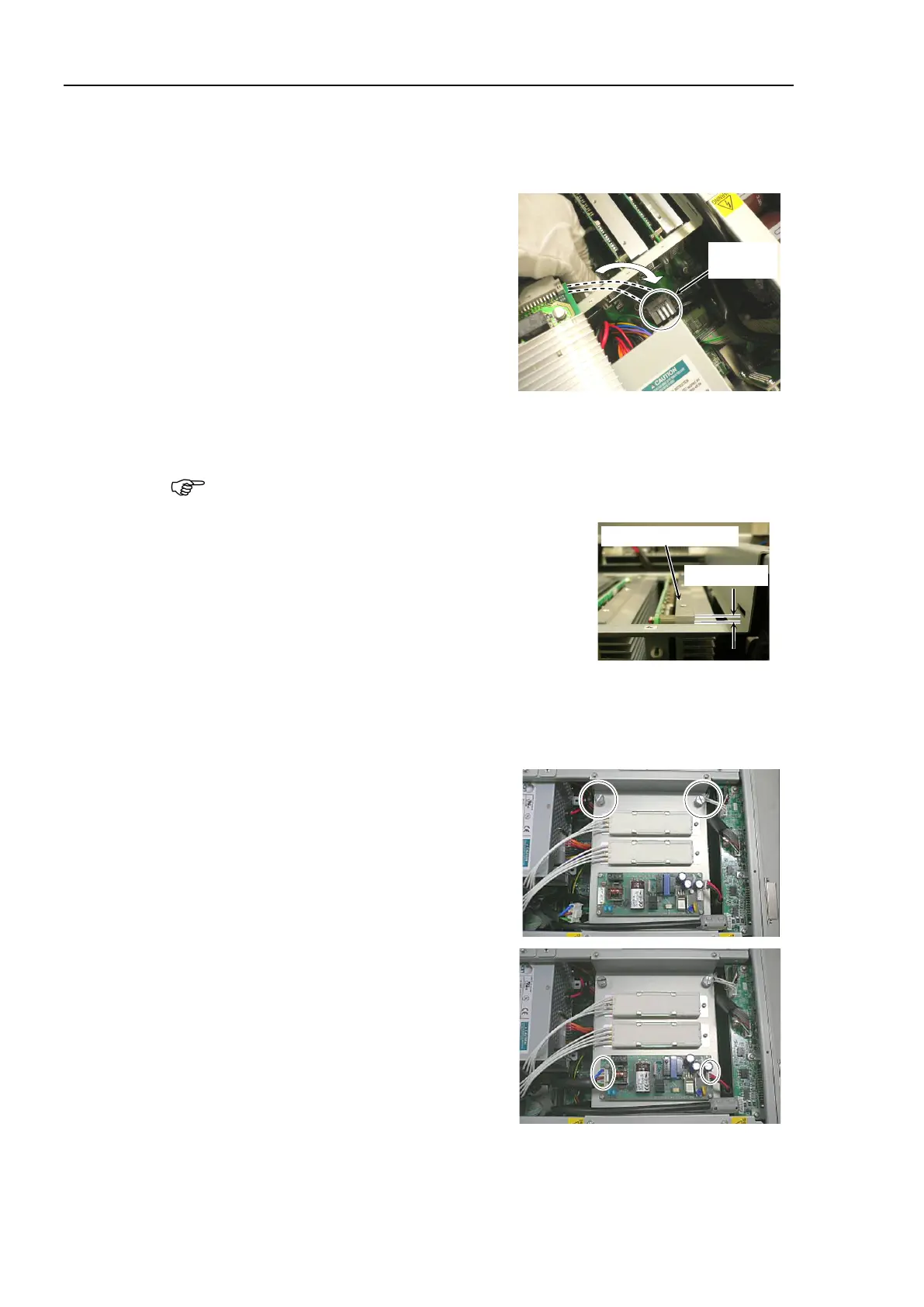
When connecting the motor driver (750
W), insert it slowly
along the guide rail,
passing the connector of motor driver
through the back of motor driver guide
plate.
Connect the motor driver connector you are replacing with the connector of cement
resistor.
There are two connectors for the cement resistor. The motor driver connector can
be connected with either one. Choose one so that you can connect easily.
Slowly insert the motor driver along the guide rail of
motor driver guide plate so that the
motor driver top
side is less than 5 mm higher than the guide plate.
Slowly slide down the motor driver so that the motor driver top side is 1 mm or less
higher than the guide plate.
mounting bracket using 5 screws.
Secure the plate, on which the switching
power supply is mounted, to the chassis
using 2 finger screws.
Connect cable No. (4) and (10) with the
switching power supply (15 W).
Maintenance:
3.2 Diagram of Cable Connections.
the top panel and secure it with 10
the power connector. Turn ON the Controller and make sure that the
Controller starts properly without any vibration or abnormal noise.
 Loading...


