Maintenance 6. Maintenance Parts Replacement Procedures
166 RC620 Rev.8
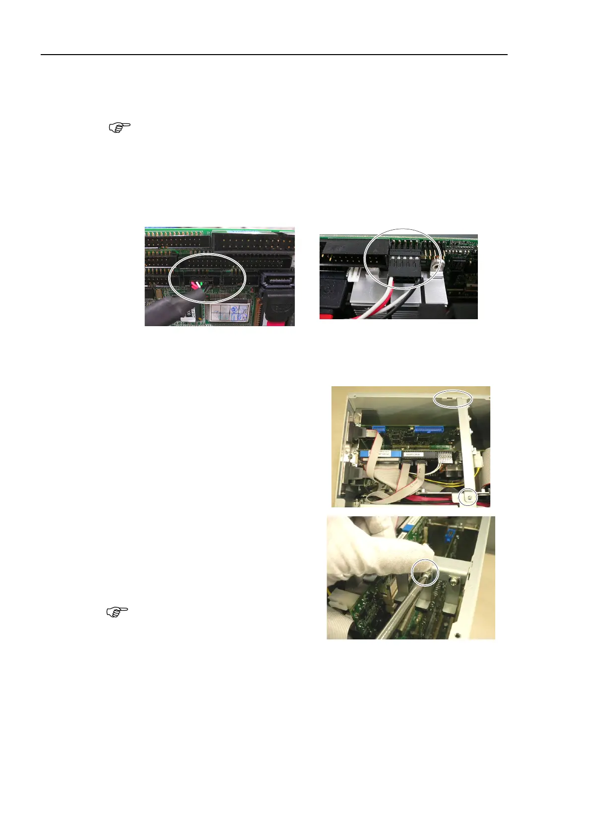
Board
Connect the following connectors holding the
CPU board near PCI-BPB.
Cable No. (19), (20), (23)
RAID option is set:
Connect Cable No. (24)
DVD drive is connected:
Connect Cable No. (25)
Maintenance: 3.2 Diagram of Cable Connections.
19) direction
CPU
’s
center (from all directions)
and connect them.
20)-1 direction
2)
er assembly into
the hole on the side panel (Right) and
secure it using a screw.
3)
Loosen a screw holding the
CPU
.
Put the CPU board in position and set
the
screw.
CPU board is firmly
er assembly for
PCI Board.)
4)
secure it using 10 screws.
If you disconnected the external cables from the CPU board, connect them again.
USB device LAN Display COM port, etc.
the power connector. Turn ON the Controller and make sure that
the
Controller starts properly without any vibration or abnormal noise.