Maintenance 6. Maintenance Parts Replacement Procedures
176 RC620 Rev.8
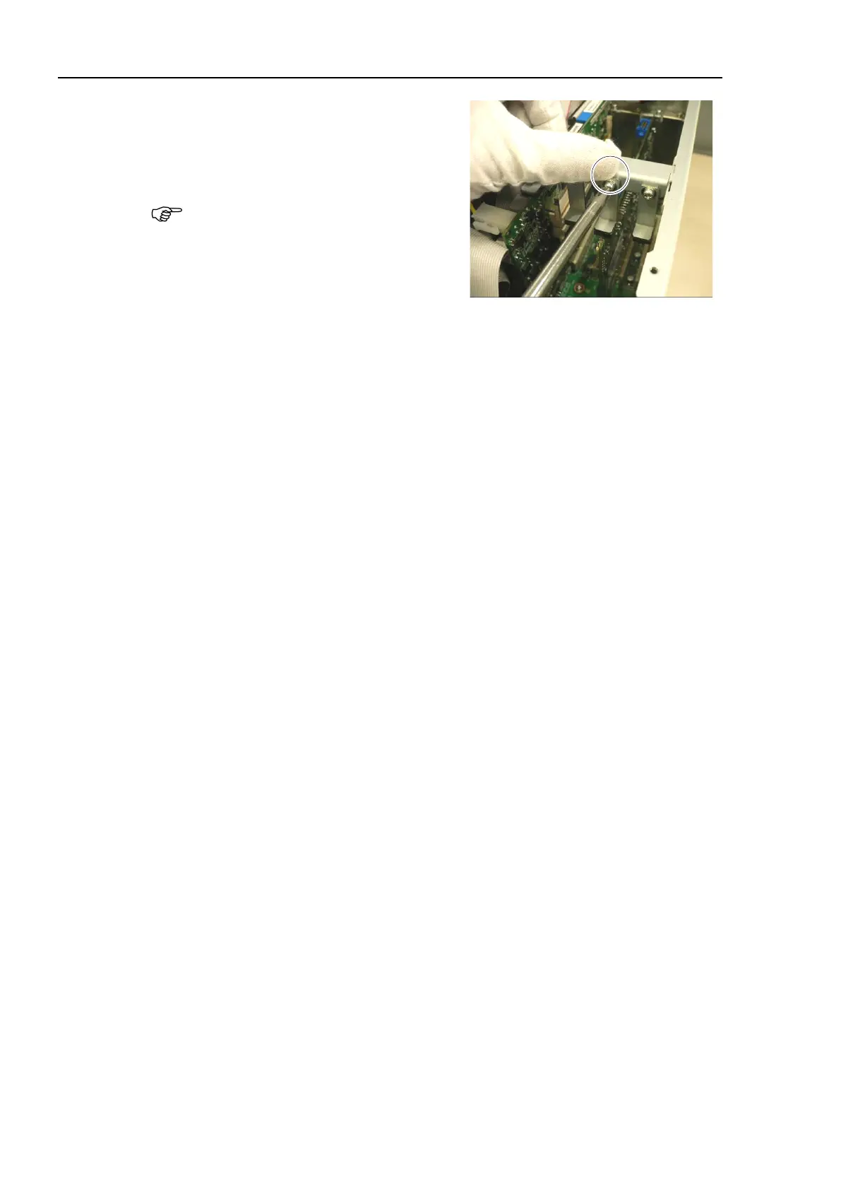
Loosen a screw holding the CPU board.
Put the CPU board in position and set the
screw.
Make sure the CPU board is firmly
placed.
er for the PCI
oard.)
Place the top panel and secure it using 10 screws.
If you disconnected the following external cables from the CPU board, connect them
again.
USB device LAN Display COM port
the power connector. Turn ON the Controller and make sure that
the
Controller starts properly without any vibration or abnormal noise.