Maintenance 6. Maintenance Parts Replacement Procedures
RC620 Rev.8 175
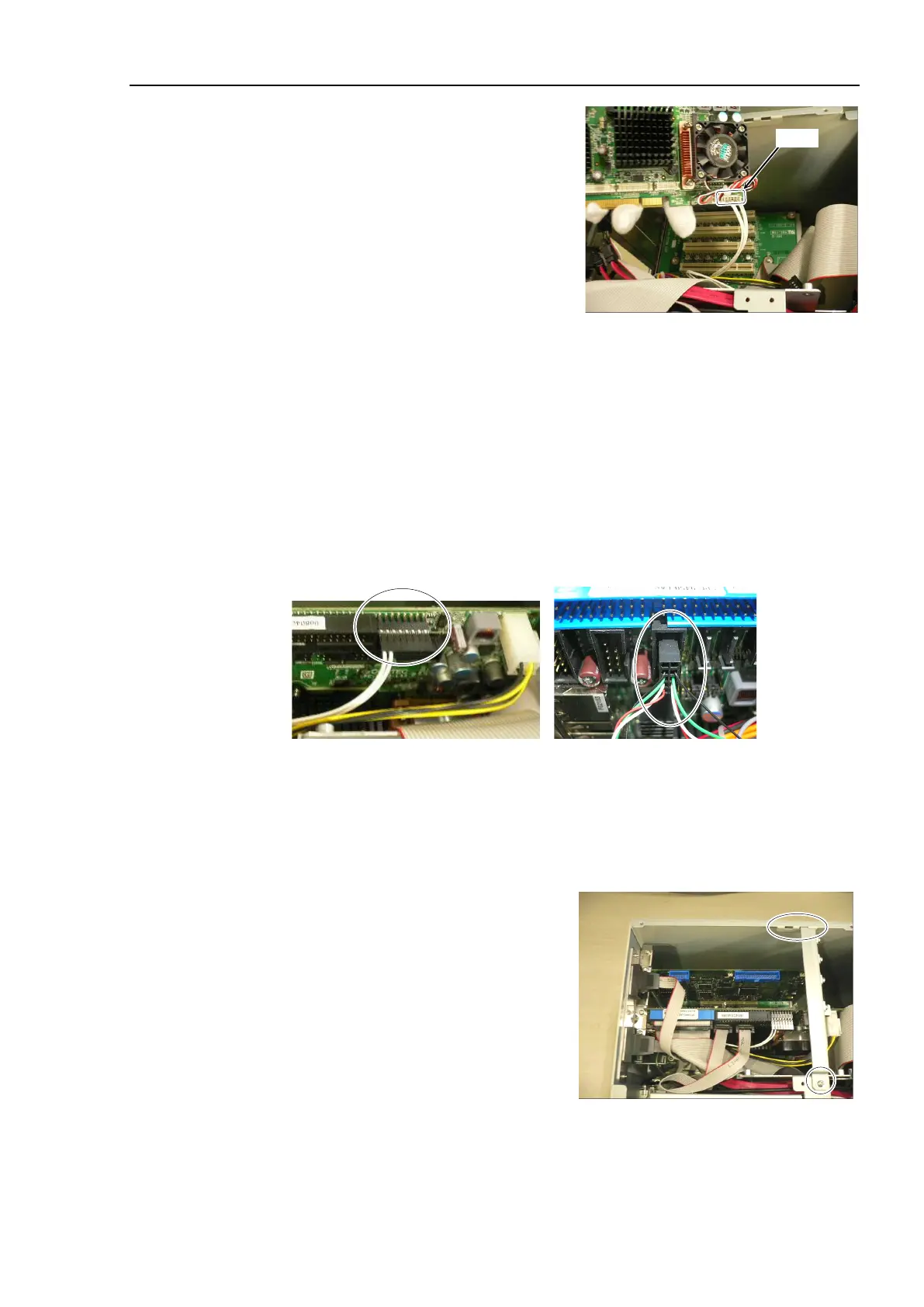
Board
1)
-3 holding the
(Faster) near PCI-BPB slot.
2)
CPU board (Faster) near PCI-BPB, connect the following connectors.
Cable No. (21), (22), (23) , COM1, 2
Connect Cable No. (24)
If DVD drive is connected:
Connect Cable No. (25)
Refer to Maintenance: 3.2 Diagram of Cable Connections.
No. (22)-2 direction
No. (21) direction
Align the pins of CPU board with the
connector
’
s center (from all directions) and
connect them.
Insert the CPU board into PCI
-BPB slot and secure it using a screw.
er assembly into the
hole on the side panel (Right) and secure
it using a screw.