Maintenance 6. Maintenance Parts Replacement Procedures
RC620 Rev.8 195
Connect the Cable No. (6) with the
Switching Power Supply
(ATX).
Refer to Maintenance:
3.2 Diagram of Cable Connections.
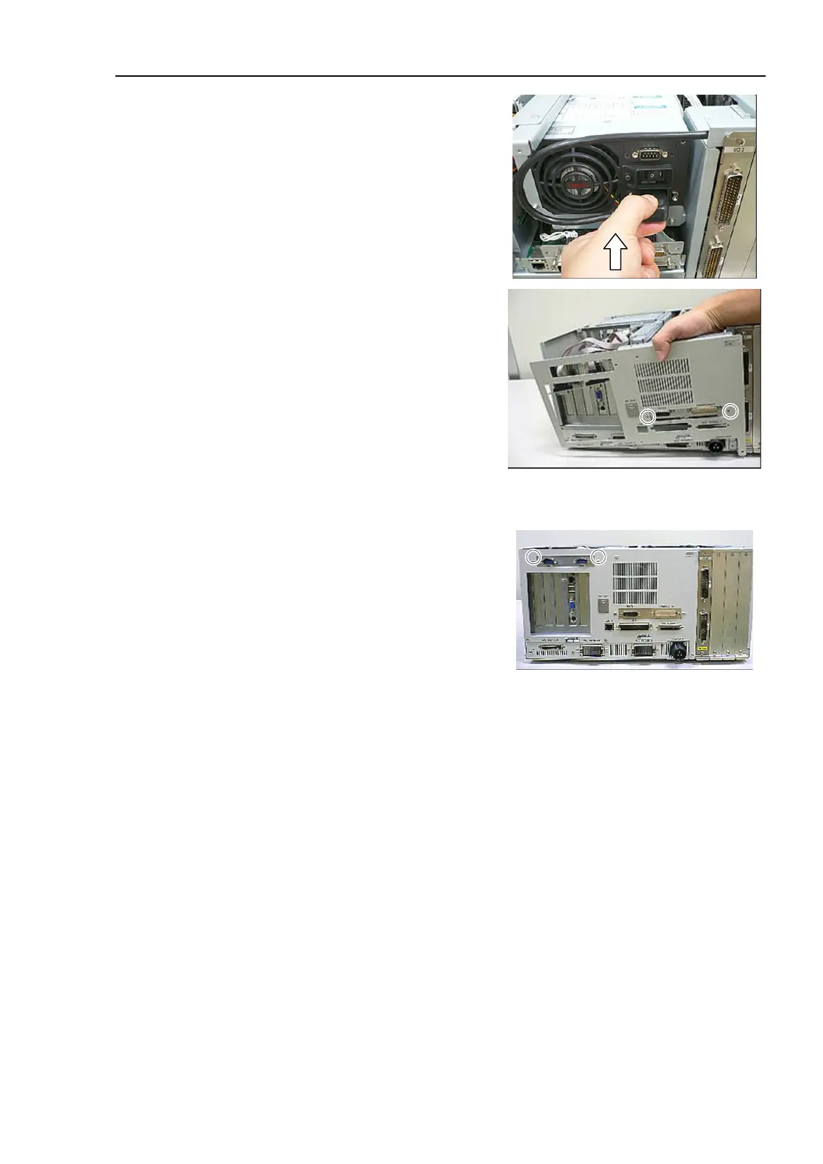
back panel as shown in the
photo and secure the plate for
EMERGENCY
connector and R-I/O
connector using 2 screws.
back panel to the Controller using 4 screws.
COM panel is mounted:
Secure the COM panel using 2 screws.
the top panel and secure it using 10 screws.
the power connector. Turn ON the Controller and make sure that the
Controller starts properly without any vibration or abnormal noise.