A maximum of 10 base units can be connected in the network configuration.
A maximum of 9 expansion modules can be connected to each base unit.
Condition 1:
During switch on (see figure):
1. The OUTPUTS on the various nodes are in the state "0" (FALSE).
2. The STOP signal is sent via the Network_Out cable.
3. If the RESET command switch on a node is actuated, all existing nodes are started when the START signal is
sent.
4. As the final result, the OUTPUT on all nodes connected has the state "1" (TRUE) if the various inputs (IN) have
the state "1" (TRUE).
5. The RUN signal is transmitted via the network to the four nodes.
Condition 2:
If the emergency stop button is pressed on one of the four nodes (see figure):
1. The OUTPUT changes to the state "0" (FALSE).
2. The STOP signal is sent via the Network_Out cable.
3. The next node receives the STOP code and deactivates the output.
4. The STOP command generates the STOP code for all lines of type Network_In and Network_Out.
5. As the final result the OUTPUT on all nodes connected is in the state "0" (FALSE).
6. If the emergency stop is switched back to the normal position, all nodes can be restarted with a single reset by transmit-
ting the START signal again. The latter condition does not occur if ENABLE RESET NETWORK is not selected. In this event
the local reset method must be used. The system needs approx. 4 seconds to restore all outputs on the blocks that
form the network.
Response time
The response time of the network starting with the emergency stop is determined using the following formula:
t
r
= [(212 ms x n° base unit)-260 ms]
The maximum number of base units connected must not be more than 10.
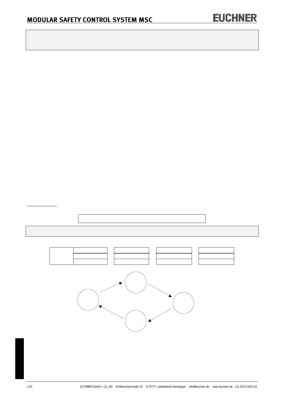
Example of a network with four nodes:
Actuation
of emer-
gency stop