Condition 3:
If the IN input on the NETWORK function block on one of the four nodes switches to the state "0"
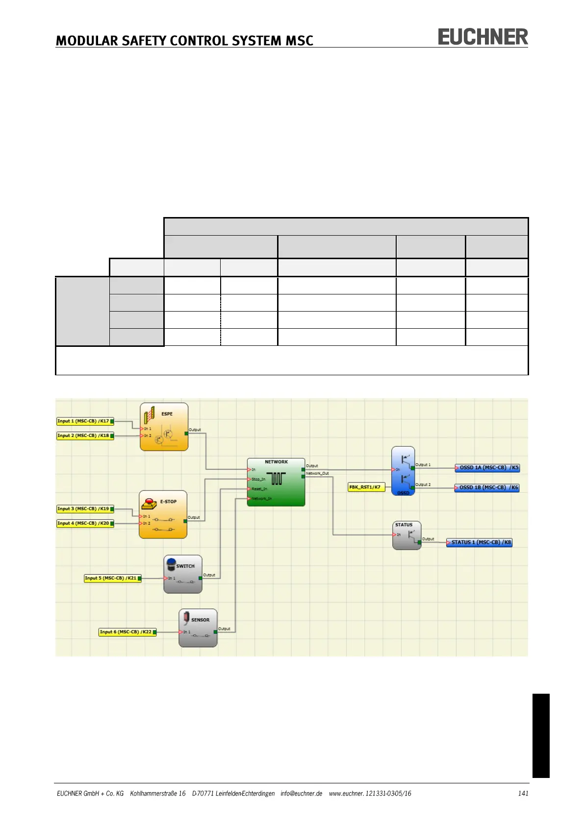
(FALSE) (see Figure 49):
1. The local OUTPUT changes to the state "0" (FALSE).
2. The RUN signal continues to be sent via the Network_Out cable.
3. The states of the other nodes remain unchanged.
4. In this event the local reset method must be used. The "Reset_In" LED flashes to indicate this state. The relat-
ed node can be restarted using its reset.
The Reset_In and Network_In inputs and the Network_Out output can only be represented on the
I/O terminals of the base unit.
SIGNALS OF THE NETWORK FUNCTION BLOCK
(1) Corresponding to the input that is connected to Network IN.
(2) Corresponding to the output that is connected to Network OUT.
(1) Corresponding to the input that is connected to Reset IN.
Figure 49 – Application example for the NETWORK function block