Installation
This section provides information on:
• Mounting the SMP351
• Rear Panel Overview
• SMP351 Rear Panel Reset
Mounting the SMP351
Before connecting the SMP351, turn off all devices that will be connected to it. The
SMP351 is housed in a 1-inch high, full-rack width metal enclosure that can sit on a table
with the provided rubber feet or can be rack mounted. Select a suitable mounting location
(see Mounting the SMP351 on page183), then choose an appropriate mounting option.
Make all external device connections before applying power.
Rear Panel Overview
100-240V 0.8 A MAX
50-60 Hz
USB STORAGE
5
4
3G/HD/SDI
INPUTS-CH A
OUTPUTS
LAN
SMP 351
REMOTE
DIGITAL I/O
MOUSE/
KEYBOARD
1
HD
DI
MP 351
EM
TE
OUSE/
EYBOARD
0-60 Hz
A
E
T
-Y
NP
T
-
H A
T
MP 35
U
E
EYB
AR
100-240V --A MAX
50-60 Hz
USB STORAGE
RESET
LAN
1
3
B-Y
R-Y VID
/Y
5
4
HDMI
3G/HD/SDI
HDMI
HDMI
AUDIO
LR
LR
LOOP THRU
2
INPUTS-CH A
INPUTS-CH B
OUTPUTS
SMP 351
1234G
DIGITAL I/O
Tx Rx
RS-232
G
REMOTE
AUDIOLR
AUDIOLR
MOUSE /
KEYBOARD
1
2
$%&'()*+
/0
-.
3412
,
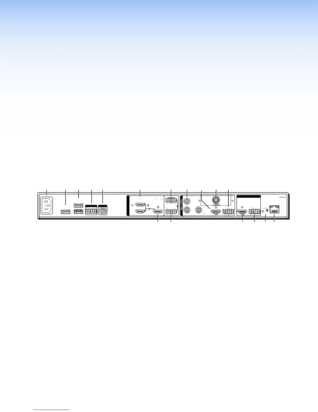
Figure 3. SMP351 Rear Panel (SMP351 3G-SDI shown)
A
100-240 VAC IEC connector for power input
J
3G/HD/SDI input card (input 5), SMP 351
3G-SDI only
B
Type A USB connector for external storage
K
3.5 mm, 5-pole captive screw connector for
channel B analog stereo audio input
C
(2) Type A USB connectors for mouse and
keyboard connection
L
HDMI loop thru from input 1 or 2
D
3.5 mm, 5-pole captive screw connector for
digital I/O
M
3.5 mm, 5-pole captive screw connector for
channel A analog stereo audio loop thru
output
E
3.5 mm, 3-pole captive screw connector for SIS
control over RS-232
N
HDMI preview output
F
HDMI inputs 1 and 2
O
3.5 mm, 5-pole captive screw connector for
analog stereo audio output
G
3.5 mm, 5-pole captive screw connector for
channel A analog stereo audio input
P
Reset button and LED
H
3 BNC connectors for component or composite
video input 3
Q
RJ-45 Ethernet connector for LAN connection
I
HDMI input 4
SMP351 • Installation 12