Input Connections
The audio and video inputs are grouped into channel A and channel B. Channel A analog
audio input can be selected for video inputs 1 or 2 (
F
). Channel B analog audio can be
selected for video inputs 3 (
H
), 4 (
I
), or 5 (
J
).
F
HDMI input (1 and 2) – Connect an HDMI (or DVI with suitable adapter) source device
to input 1 and input 2.
NOTE: Channel A (inputs 1 and 2) is optimized for full
range sources such as PCs. When using a video source
with adjustable quantization range on these inputs, select
"Full Range" for the most accurate video reproduction.
G
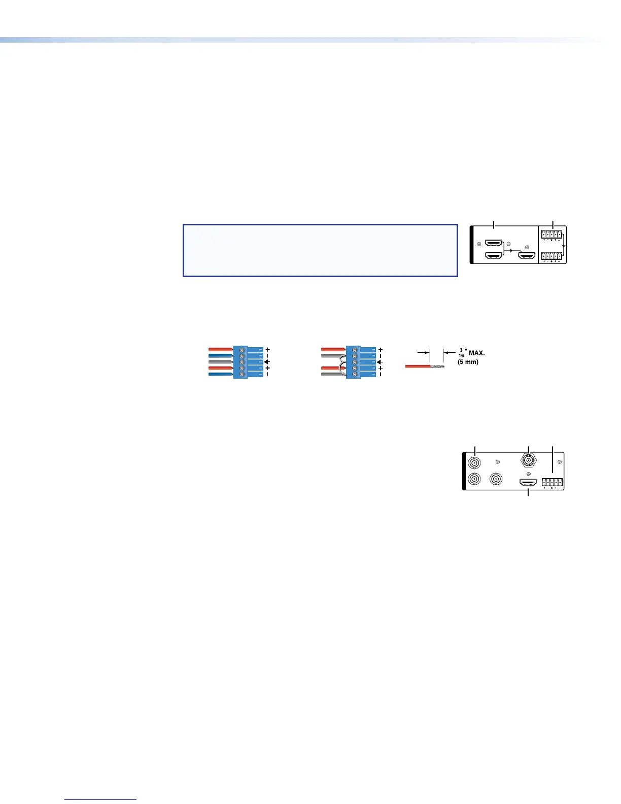
Channel A analog audio input – Connect a balanced or unbalanced stereo line level
audio device to this 5-pole, 3.5 mm captive screw connector. Channel A audio can be
selected for output with HDMI inputs 1 and 2 instead of the embedded audio. Wire the
connector as shown in figure 4.
Unbalanced Stereo InputBalanced Stereo Input
(high impedance)(high impedance)
Do not tin the wires!
Tip
Slee
ve(s)
Ring
Ring
Tip
Left
Right
Sleeve
Sleeve
Tip
Left
Right
Figure 4. Audio Input Captive Screw Connector Wiring
H
Analog video input 3 – Connect component video to
the three BNC connectors (B-Y, R-Y, VID/Y). Connect a
composite video signal to the VID/Y BNC connector.
I
HDMI input 4 – Connect an HDMI (or DVI with suitable
adapter) source device to input4.
J
Serial digital video input 5 (SMP 351 3G-SDI only) –
Connect a 3G/HD/SDI video signal to this BNC connector.
K
Channel B analog audio input – Connect a balanced or unbalanced stereo line level
audio device to this 5-pole, 3.5mm captive screw connector. Channel B audio can be
selected from either the HDMI embedded audio, ChB analog audio, or the audio can
be set to Off. Wire the connector as shown in figure 4.
3
B-Y
R-Y VID
/Y
5
4
HDMI
3G/HD/SDI
AUDIO
,
1
HDMI
AUDIO
LOOP THRU
2
Power Connection
A
100-240 VAC power input – Connect the provided IEC cord. Verify the front panel
buttons and LCD illuminate (see Front Panel Features on page18).
SMP351 • Installation 13