Output Connections
L
HDMI loop-thru output – Connect an HDMI (or DVI with suitable adapter) display
device to the HDMI Loop Thru connector to view the selected input 1 or input 2.
M
Audio loop output – Connect a balanced or unbalanced stereo line level audio device
to this 5-pole, 3.5 mm captive screw connector (see figure 3,
M
on page 12). Wire
the connector as shown in figure 5. Audio is always from audio input
G
.
ATTENTION:
• For unbalanced audio, connect the sleeves to the ground contact. DO NOT
connect the sleeves to the negative (–) contacts.
• Pour l’audio asymétrique connectez les manchons au contact au sol. Ne PAS
connecter les manchons aux contacts négatifs (–).
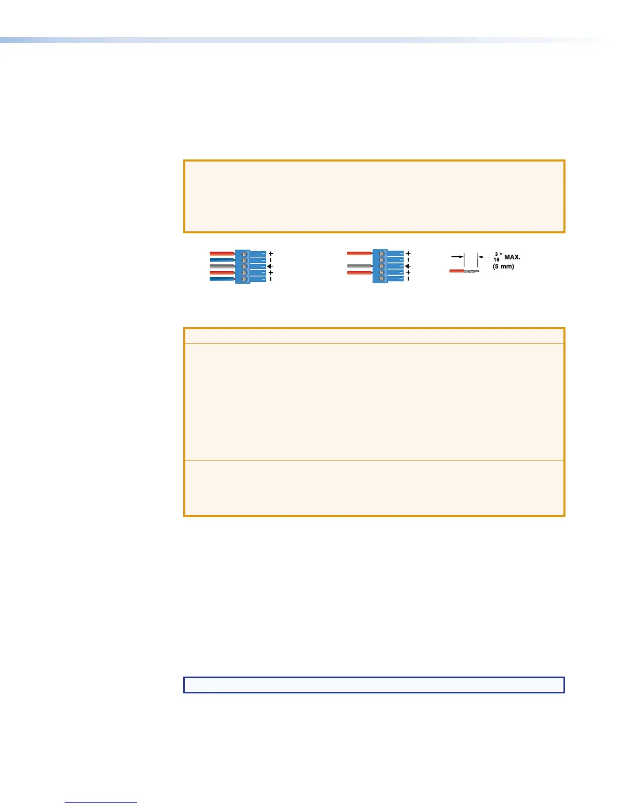
Balanced Audio Output Unbalanced Audio Output
Do not tin the wires!
Left
Tip
Sleeve(s)
NO Ground Here
NO Ground Here
Tip
Right
Tip
ve(s)
Ring
Ring
Tip
Left
Right
Figure 5. Audio Output Captive Screw Connector Wiring
ATTENTION:
• The length of the exposed wires in the stripping process is important. The ideal
length is 3/16 inch (5 mm). If longer, the exposed wires may touch, causing a
short circuit between them. If shorter, the wires can be easily pulled out even if
tightly fastened by the captive screws.
• La longueur des câbles exposés est importante lorsque l’on entreprend de les
dénuder. La longueur idéale est de 5mm (3/16inches). S’ils sont un peu plus
longs, les câbles exposés pourraient se toucher et provoquer un court circuit.
S’ils sont un peu plus courts, ils pourraient sortir, même s’ils sont attachés par
les vis captives.
• Do not tin the wires. Tinned wires are not as secure in the captive screw
terminals and could pull out.
• Ne pas étamer les câbles. Les câbles étamés ne sont pas aussi bien fixés
dans les terminaisons des à vis captives et pourraient sortir.
N
HDMI preview output – Connect an HDMI (or DVI with suitable adapter) display
device to this HDMI output connector. Using an attached USB keyboard and mouse,
the Preview Output can be switched beween a preview of the recorded content and an
internal browser client.
O
Analog Audio output – Connect a balanced or unbalanced stereo line level audio
device to this 5-pole 3.5 mm captive screw connector (see figure 5) for select audio
output. Wire the connector as shown in figure 5.
The audio output depends both on the input selection and either the embedded audio
or analog audio as selected for that input (see Audio Select on page38). Audio
output is selected from channel A, from channel B, or a mix of both channel A and
channel B.
NOTE: The default audio channel is channel B.
SMP351 • Installation 14