Progress bar
EE
FF
II
K
K
J
J
Input 5
Input 4
Input 1
Input 2
Input 3
Auto-Image
Video Mute
Audio Mute
Mute All
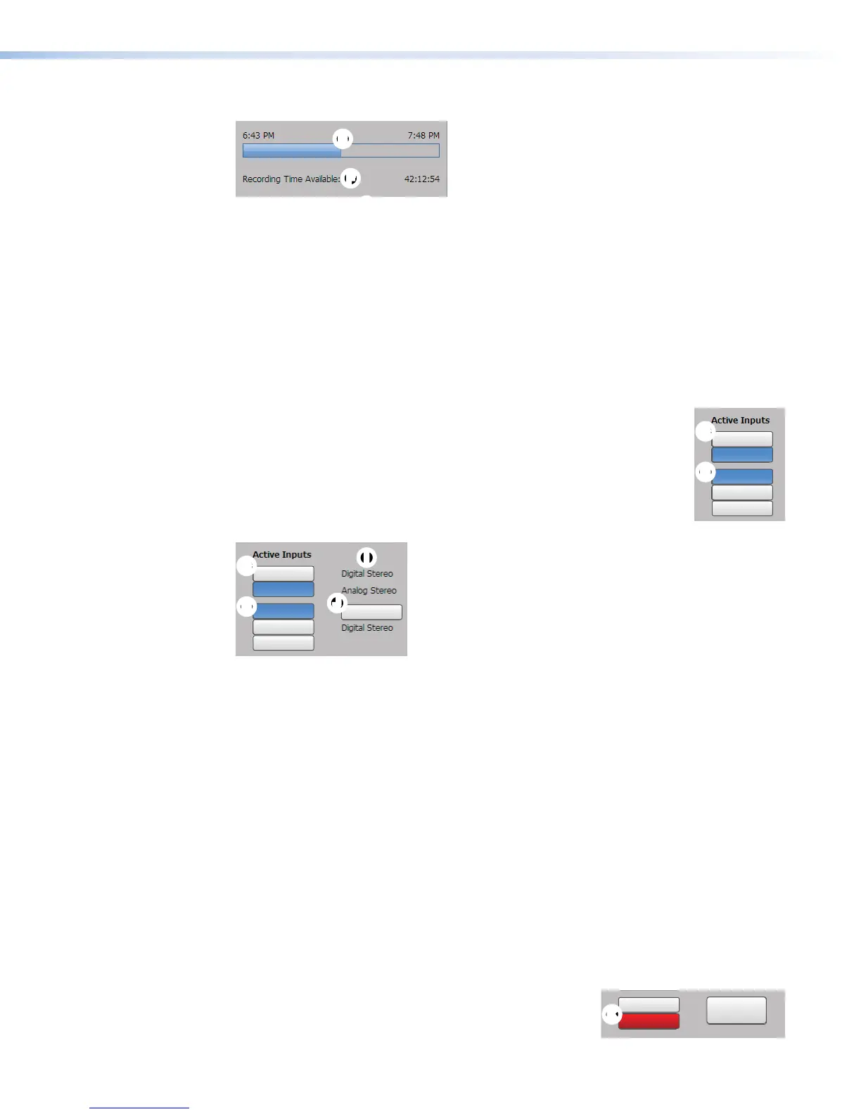
A progress bar (
E
) below the recording control buttons is a horizontal bar graph that shows
how much recording time has elapsed and, if it is a scheduled session rather than an adhoc
recording, how long the presentation is expected to last.
Recording time available
Available recording time (
F
) is indicated below the progress bar. How much time is available
is based on the combination of available storage space and the current stream resolution
and bit rate.
Input selection
Inputs are grouped into two channels:
• Input 1 (HDMI) and input 2 (HDMI) form channel A (
G
)
• Input 3 (component/composite), input 4 (HDMI), and optional input 5
(3G/HD/SDI) form channelB(
H
).
There is one analog audio input per channel. HDMI inputs can be
configured for digital audio (embedded in HDMI) or a shared analog input
for the channel. The audio type for each input is displayed in the right
column (
I
).
GG
H
H
II
JJ
Input 5
Input 4
Input 1
Input 2
Input 3
Auto-Image
Video Mute
Audio Mute
Mute All
Audio mode (digital stereo or analog stereo) must be configured in the Input/Output
Settings page (see Input/Output Settings on page75).
• By default these input buttons are labeled Input 1, Input 2, Input 3 , Input 4, and Input5.
To change the button text, see Input/Output Settings on page75.
• Video input types are fixed per input, except for the format of component or composite
video input for input 3 (see Configuring inputs on page76).
• Buttons for active inputs are blue. Buttons for inactive inputs are gray.
To select AV sources:
1. Click the input buttons in the left column of the Active Inputs panel to select
AVsources for a presentation. Input changes take effect immediately and reflect in the
preview.
2. To apply Auto-Image to input 3, click Auto-Image to the right of Input 3 (
J
).
Auto-Image automatically sizes and centers the selected input to match the channel B
window.
Mute buttons — Click the desired button (
K
) to mute video only (Video Mute), audio only
(Audio Mute), or both audio and video (Mute All).
When a mute mode is selected (active), the corresponding
button or buttons are red. Click the buttons to toggle mute
states, use the front panel controls, or send SIS commands
to the unit via RS-232 or USB control.
GG
H
H
Input 5
Input 4
Input 1
Input 2
Input 3
Auto-Image
Video Mute
Audio Mute
Mute All
KK
JJ
Input 5
Input 4
Input 1
Input 2
Input 3
Auto-Image
Video Mute
Audio Mute
Mute All
SMP351 • Web-Based User Interface 55