Chapter 8 System Operation
PAGE 8- 32
8-7-2 System Parameters
D-No.000
Torque Unit
All fastening parameters within the Controller will have the same torque unit.
Unit
N
・
m
kgm kgcm Ftlbs Inlbs
D-No.001
Firmware Version
Version of the controller Firmware
D-No.002
Amplifier Version
Version of servo amplifier Firmware
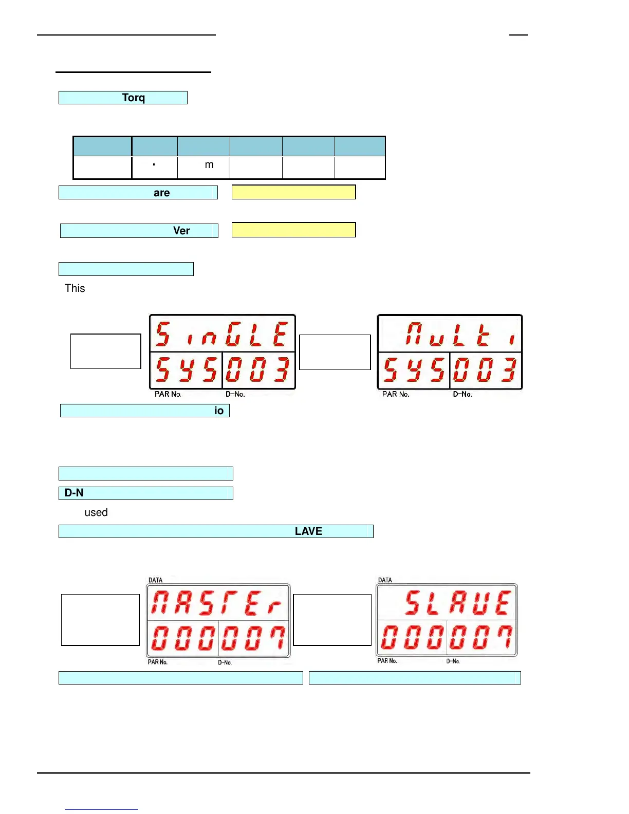
D-No.003
System Type
This is used for switching between the multi system and single system.
Refer to Section 8-5 “System Change-Over” for more details.
D-No.004
External Gear Ratio Standard setting: 1.000, Setting range: 0.300 to 3.000
Used to adjust the gear ratio when an external head (that has a gear ratio other than 1:1) is connected to
the output shaft of the tool. Do not use a value other than the standard setting (1.000) unless an external
offset gear is attached.
D-No.005
In-house adjustment
D-No.006
In-house adjustment
Not used.
D-No.007
Axis Communication (MASTER, SLAVE) Display
This indicates whether the controller is the MASTER (for (PC) communication and I/O (PLC)
communication) or SLAVE spindle.
D-No. 008 Controller Cycle Count (×1 million) D-No. 009 Controller Cycle Count (×1)
Indicates the number of fastening cycles the controller has performed.
* When the count is less than 1 million, [------] is indicated for D-No. 008.
MASTER
(Master
Spindle)
SLAVE
(Slave
Spindle)
Single
System
Multi
System