Chapter 8 System Operation
PAGE 8- 35
[System Parameters – continued]
D-No. 200 Controller Setup Tool No.
Setting range: Tool No. registered for the model
The Tool No. of the connected tool is set with reference to “Tool Models” on Section 2-2-3. When the
controller tool No. is changed, initialization and automatic correction of the fastening parameter set
values are performed.
D-No. 201 Controller Setting Tool Information
The tool and motor model number setup in the parameter (at D-No. 200) are indicated.
(ex. “101rs1”)
D-No. 202 Parameter Setting File Version
The version of the parameter file set in the controller is indicated.
D-No. 203 Sequence Setting File Version
The version of the sequence file set in the controller is indicated.
D-No. 204 PLC Output Layout Setting File Version
The version of the PLC output layout file set in the controller is indicated.
D-No. 205 Fieldbus Setting File Version
The version of the fieldbus file set in the controller is indicated.
D-No. 206 Fieldbus Message Setting File Version
The version of the fieldbus message file set in the controller is indicated.
D-No. 207 RS232C Input/Output Setting File Version
The version of the RS232C input/output set in the Controller is indicated.
D-No. 208 Controller RS232C Communication Speed [bps]
The communication speed of the RS232C interface on the controller front panel is indicated.
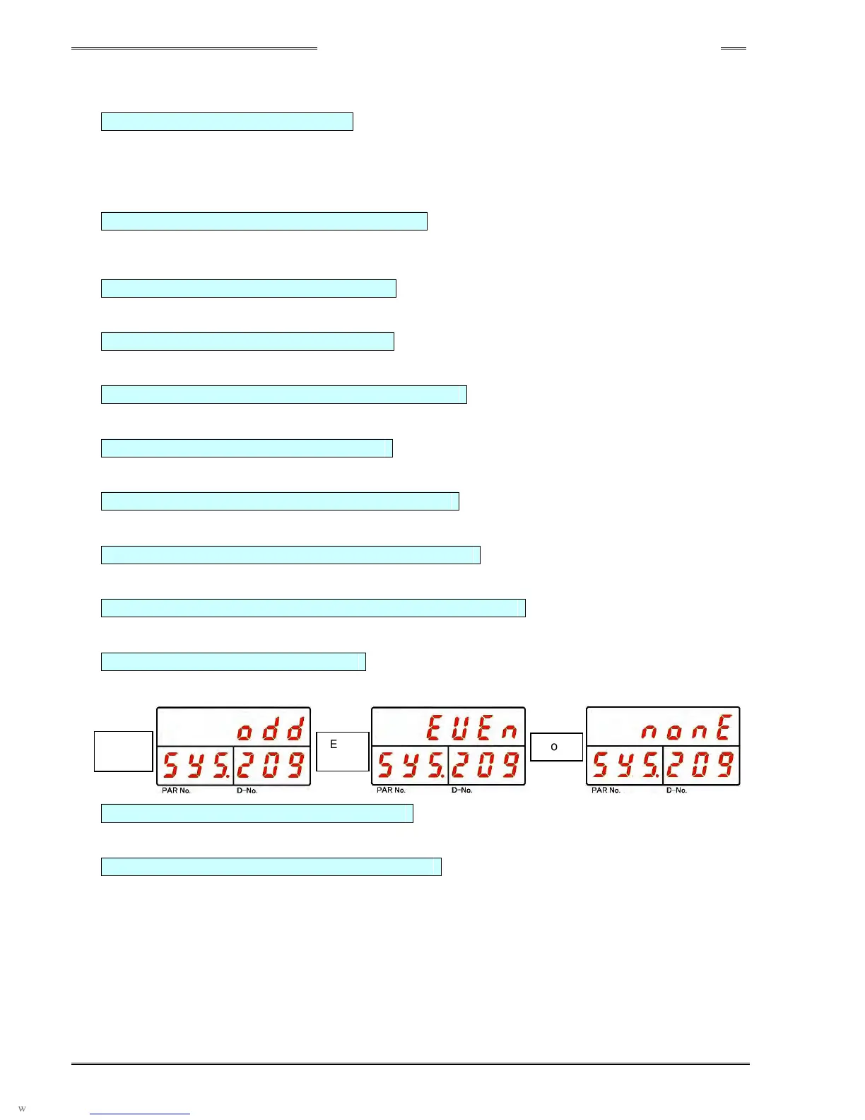
D-No. 209 Controller RS232C Parity
The parity of the RS232C interface on the controller front panel is indicated.
D-No. 210 Controller RS232C Stop Bit [bit]
The stop bit of the RS232C interface on the controller front panel is indicated.
D-No. 211 Controller RS232C Data Length [bit]
The data length of the RS232C interface on the controller front panel is indicated.
Odd
Even
None