Chapter 3 System Description
PAGE 3-28
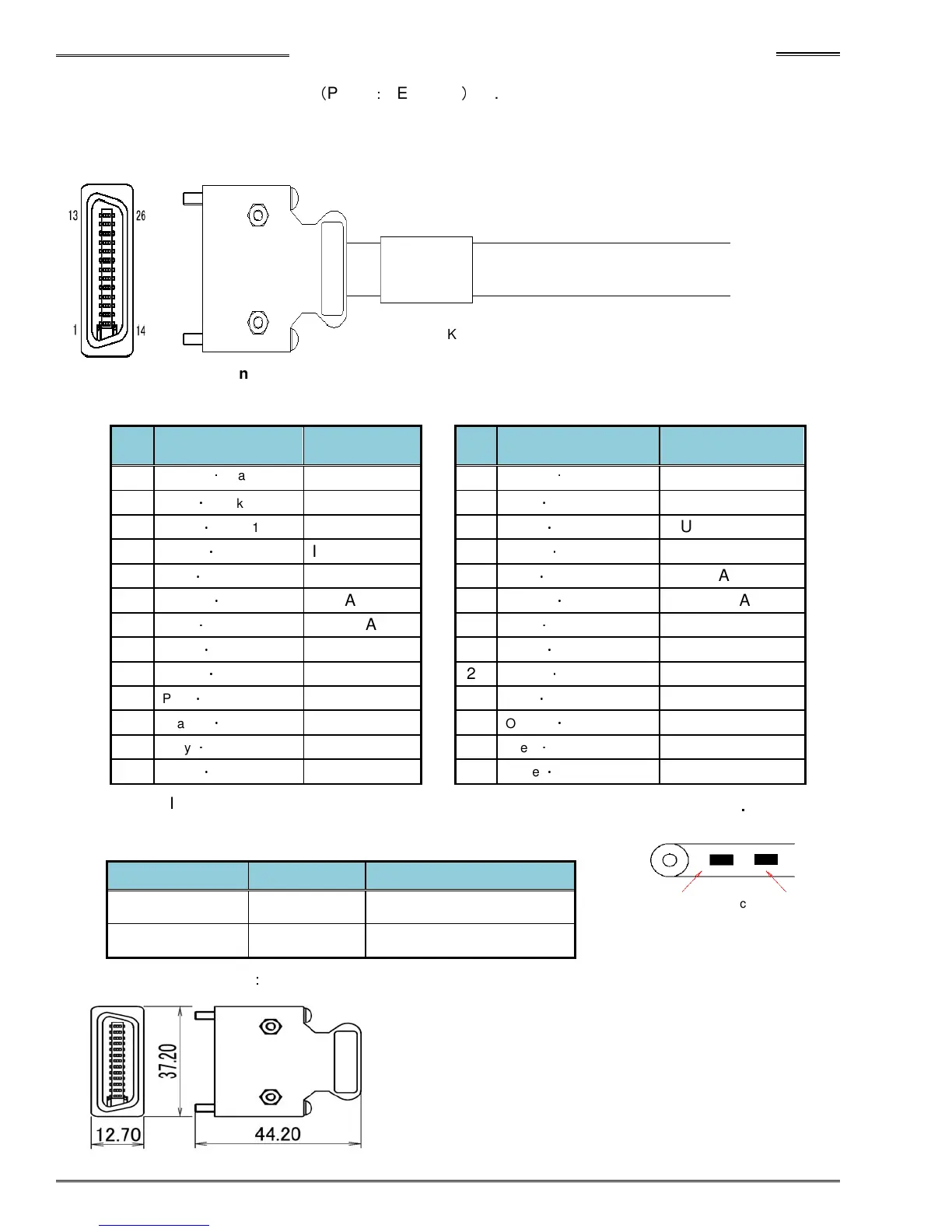
■ I/O Cable (For standard unit)
(
Part #
:
FEB-1634
)
9.8 Feet Long
* This cable can only be used on the standard MFC unit front panel (I/O connector)
●Drawing for outside view of cables
●Connector pin assignment
Pin
No.
Wire Color Description Pin
Wire Color Description
1
Orange
・
Black 1
IN COMMON
14
Orange
・
Red 1
OUT COMMON
2
Grey
・
Black 1
IN DATA1
15
Grey
・
Red 1
OUT DATA1
3
White
・
Black 1
IN DATA2
16
White
・
Red 1
OUT DATA2
4
Yellow
・
Black 1
IN DATA3
17
Yellow
・
Red 1
OUT DATA3
5
Pink
・
Black 1
IN DATA4
18
Pink
・
Red 1
OUT DATA4
6
Orange
・
Black 2
IN DATA5
19
Orange
・
Red 2
OUT DATA5
7
Grey
・
Black 2
IN DATA6
20
Grey
・
Red 2
OUT DATA6
8
White
・
Black 2
IN DATA7
21
White
・
Red 2
OUT DATA7
9
Yellow
・
Black 2
IN DATA8
22
Yellow
・
Red 2
OUT DATA8
10
Pink
・
Black 2
IN DATA9
23
Pink
・
Red 2
OUT DATA9
11
Orange
・
Black 3
IN DATA10
24
Orange
・
Red 3
OUT DATA10
12
Grey
・
Black 3
IN DATA11
25
Grey
・
Red 3
OUT DATA11
13
White
・
Black 3
IN DATA12
26
White
・
Red 3
OUT DATA12
* See PLC I/O Signals (2-2-3) for signal definition
●Connector Model (Controller side)
Type
Connector Cover
Sumitomo 3M
10326-52A0-008 (26 pin)
Connector Plug Sumitomo 3M
10126-3000PE
●Connector Size (Unit
:
mm)
Controller Side
(Ref. DDK Part # C30-SU1-M3 M3=Length in meters)
(Misumi #SHPM-HY-SB-26-3-02S-00F)
* Example: Orange
・
Black 2
Wire color: Orange Black dots: 2 dots