FT-111, User Manual Rev. 2.0.0, June 2022 Page 103 of 137
11.10 PROFINET
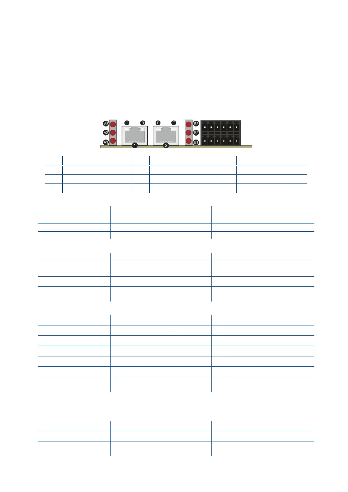
Profinet interface of the weighing instrument can be done via hub switch or serial bus over two Profinet port.
1. Serial bus connection of instruments. You may connect instruments serial to your Profinet bus
via two ports.
2. Star connection. If you connect the instrument to your PLC via hub switch, you can use P1 or P2
port on the instrument. You may change the port if there is any malfunction on port in usage.
The Profinet interface is 100Mbit and full duplex. GSDML file for two port Profinet is on www.flintec.com
There are a few announcement LEDs on the instrument to indicate the interface status as seen below.
A1 Network Status LED
Not power or not initialized
No power or Profinet module is in
initialization state
Initialized, diagnostic
event(s) present
There is an exception error
Check GSDML configuration
Re-energize the instrument.
If seen again, change the board.
In the case of LED warning, check cabling, configuration, IP address and device name. Power off the
instrument and reenergize the instrument 30 seconds later.
C, E LINK/Activity LED
No link, no communication present
Ethernet link established, no
communication present
Interface ports ( P1,P2 )