FT-111, User Manual Rev. 2.0.0, June 2022 Page 91 of 137
11.6 ANALOGUE OUTPUT
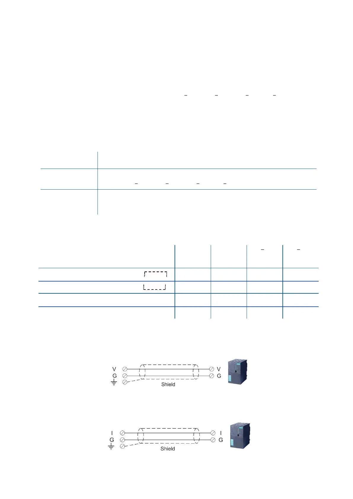
IMPORTANT NOTE: The analogue output cable should be shielded. Connect the shield to the protective earth
as described in the installation section.
PARAMETERS: Sub-block 19- for analogue output set up.
FT-111 has analogue output which is programmable to 4 20 mA, 0 20 mA, 0 5 V or 0 10 V. Analogue
output is automatically adjusted to the weighing range after the calibration. The mid value of the analogue
output is set to zero load at bipolar usage. The manual analogue output adjustment is available in parameter
group 19- .
The analogue output is related with the gross or net load of the scale (default is gross). The analogue output
signal operates as described below.
When the gross indication drops below zero, the analogue output reduces the
analogue output to 0mA or - 4 V to indicate error on the analogue output.
The analogue output will reflect the gross value to the programmed analogue
output 4 20 mA, 0 20 mA, 0 5 V or 0 10 V.
When the gross value exceeds the high limit, the analogue signal increase to
approximately 24 mA or 11 V and remains there until the weight display is no
longer blanked or the analogue signal returns to within range.
The following table indicates the analogue output value when the gross indication is out of the range and if
there is any error indication on the display.
The weight is more than the range ( )
The weight is under the zero range ( )
ADC is out of operating range ( LC Err )
The error data indicated above can be used to follow the errors at PLC.
11.6.1 Analogue Output Connection
Figure 11.4 - Voltage output connections
Figure 11.5 - Current output connection