FT-111, User Manual Rev. 2.0.0, June 2022 Page 16 of 137
Warning: Incorrectly closed back cover and poorly tightened glands may be unwanted results with loss of IP
4.1.4 Electrical Connection Recommendations
1. Always remember that FT-111 terminal is very low voltage measuring instrument used in the
industrial environment. Your proper installation increases the reliability and performance of the
instrument.
2. Only a trained person should interface the instrument due of the 230 VAC voltage in the instrument
and against malfunction at installation.
3. If the energy condition of your plant is not good enough, prepare a special power line.
4. The quality of your plant grounding will provide weighing accuracy and the safety of FT-111. If
grounding of your plant is not good enough, prepare a special power line and grounding.
5. Power off the instrument before connecting or disconnecting any peripheral instrument.
6. The shielded cable and ground connection of the shield will increase the immunity of FT-111 against
electrical disturbances. Shields of cables should be connected to the grounding pins in
FT-111.
7. All required electrical connections should be done as described in the installation section, page 17.
If you need to service the terminal, turn the power off and wait at least 30 seconds before opening
housing.
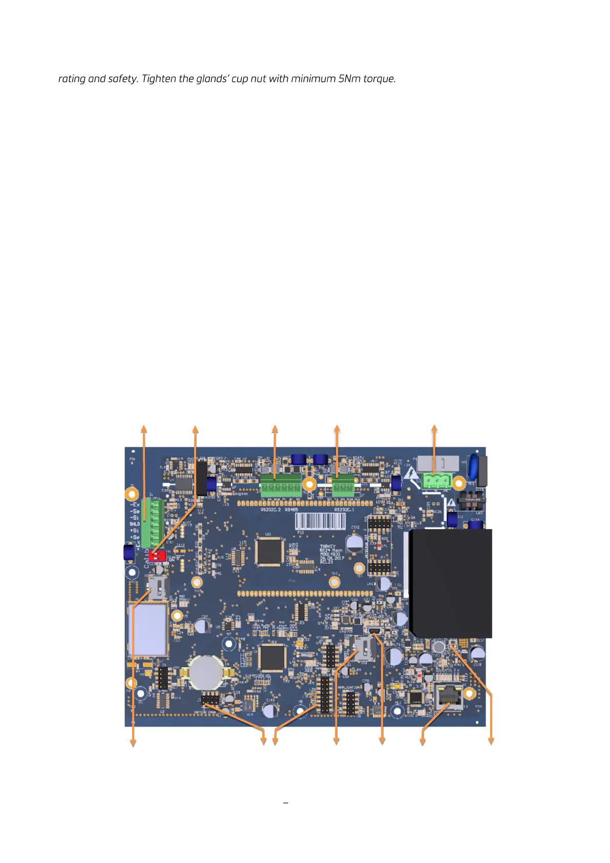
Location of the Peripheral Connections
The electrical terminals of the main board are shown in the 2 pictures below.
Figure 4.3 FT-111 main board