FT-111, User Manual Rev. 2.0.0, June 2022 Page 116 of 137
11.14 POWERLINK
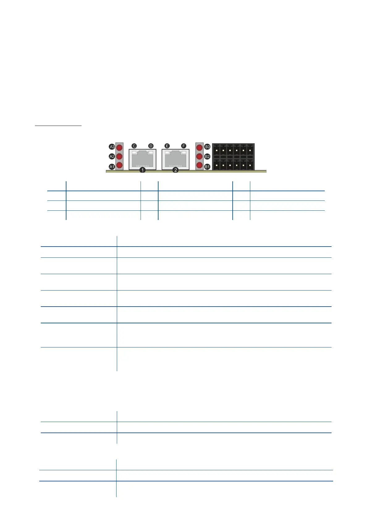
Powerlink interface of the weighing instrument can be done via hub switch or serial bus over two Powerlink
port.
1. Serial bus connection of instruments. You may connect instruments serial to your Powerlink bus
via two ports.
2. Star connection. If you connect the instrument to your PLC via hub switch, you can use P1 or P2
port on the instrument. You may change the port if there is any malfunction on port in usage.
The Powerlink interface is 100Mbit and half duplex. XDD file for two port Powerlink is available on
www.flintec.com
There are announcement LEDs on the instrument to indicate the interface status as seen below.
A1 Network Status LED
Module is off, initializing, or not active.
NMT_CS_BASIC_ETHERNET
Basic Ethernet state: no POWERLINK traffic has been detected.
NMT_CS_PRE_OPERATIONAL_1.
Only asynchronous data.
NMT_CS_PRE_OPERATIONAL_2.
Asynchronous and synchronous data. No PDO data.
b
NMT_CS_READY_TO_OPERATE.
Ready to operate. Asynchronous and synchronous data. No PDO data.
b
NMT_CS_OPERATIONAL.
Fully operational. Asynchronous and synchronous data. PDO data is sent
and received.
NMT_CS_STOPPED
Module stopped (for controlled shutdown, for example). Asynchronous and
synchronous data. No PDO data.
b
a. On 50 ms, off 50 ms.
b. Any process data sent is declared not valid and received process data must be ignored in this state.
c. On 200 ms, off 200 ms.
A3 Network Error LED
If the MODULE ERROR LED also is On, a fatal event was encountered.
If the NETWORK ERROR LED is Off, a non-fatal error has been detected.
If the NETWORK ERROR LED is On, a fatal event was encountered.
Interface ports ( IN, OUT )