FT-111, User Manual Rev. 2.0.0, June 2022 Page 93 of 137
11.7 MODBUS RTU
FT-111 controller has a Modbus RTU interface over RS485 / RS232C serial port. This interface can be
programmed to High-Low or Low-
data formats and some companies using these formats. Two types are available as:
11.7.1 Modbus RTU Data Structure
After programming RS485 / RS232C serial port for Modbus RTU, it can be used as a Modbus RTU slave on
Modbus RTU network. The Modbus slave address is defined in the RS-485 address (Page 48). Functions code
Modbus RTU High-Low: In two-word registers, the data is stored to the registers in big-endian format. Least
significant word is stored to the highest register address; and most significant word is stored to the lowest
register address.
Modbus RTU Low-High: In two-word registers, the data is stored to the registers in little-endian format.
Least significant word is stored to the lowest register address; and most significant word is stored to the
highest register address.
-up:
Set the RS 485 / RS 232C Data Format : Modbus RTU High-Low or Modbus RTU Low-High
RS-485 Data Length & Parity : 8 none 1, 8 odd 1 or 8 even 1
RS-485 Address : 01 to 31
Make the RS-485 / RS 232C parameter settings as defined on Page 46, 47, 48
.
Please find Modbus information in the web site of http://www.modbus.org
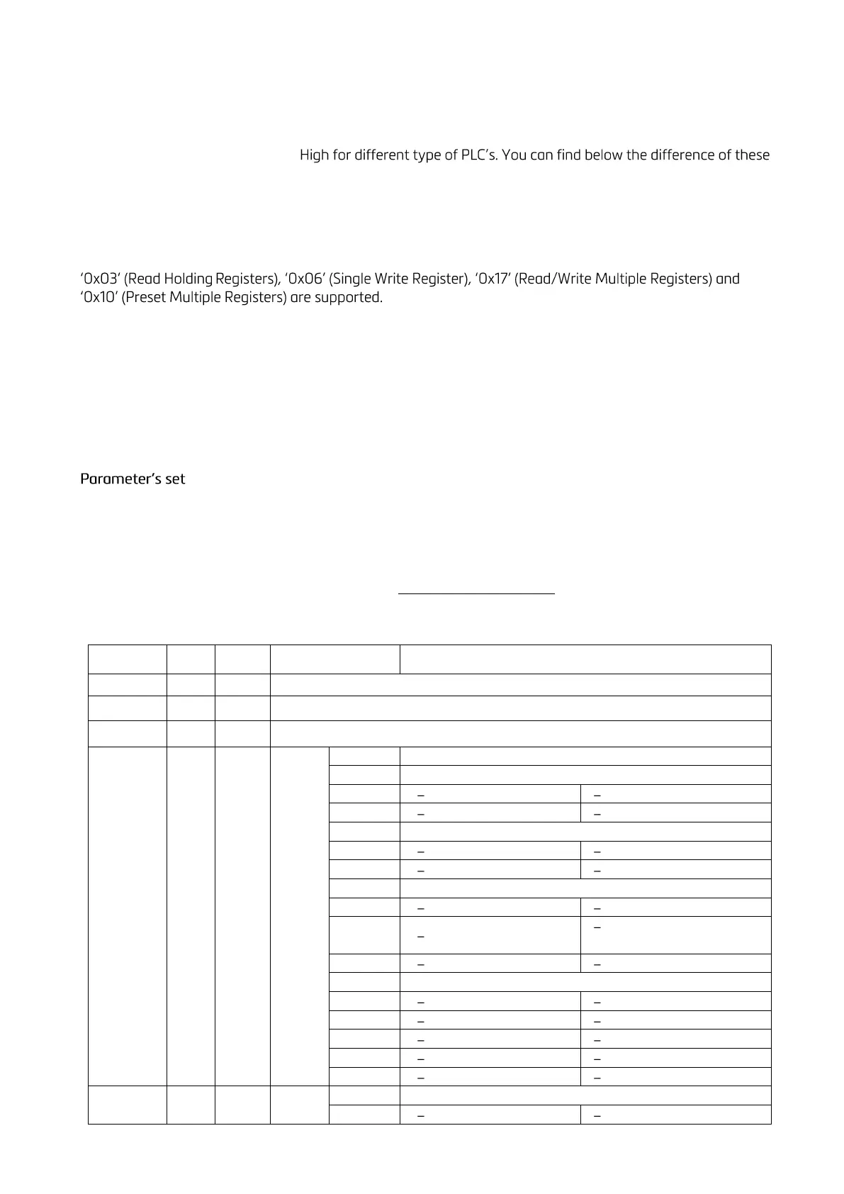
Modbus RTU and TCP/IP Command Table: