FT-111, User Manual Rev. 2.0.0, June 2022 Page 102 of 137
PROFIBUS Connector pin configuration (DB9F)
Positive RxD / TxD, RS-485 level
+5V termination power (isolated)
Negative RxD / TxD, RS-485 level
Pin configuration of digital input and output connector is described on page 76.
11.9.2 Data Format
Data format of weight value can be programmable for Floating point (IEEE 754) or Integer. Refer to
parameter [ 191 ].
11.9.3 GSD Configuration
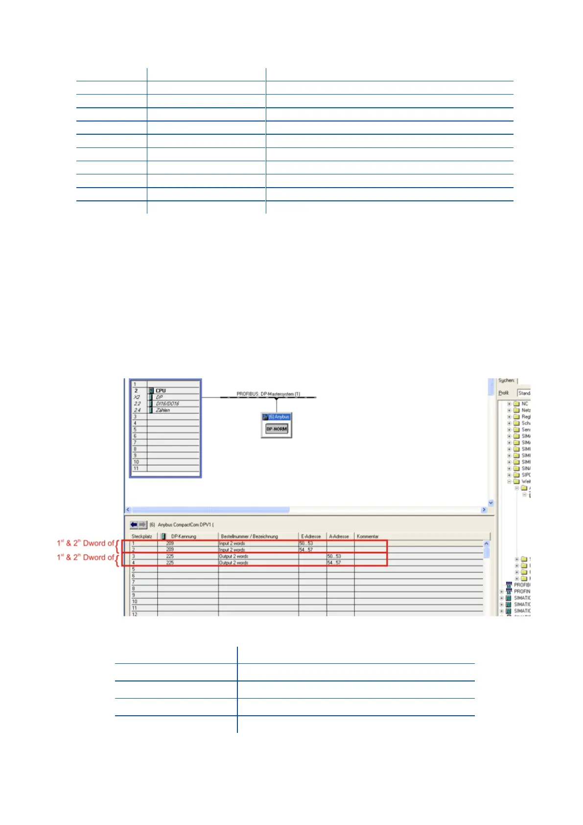
Profibus data consist of 2 pcs Input-2 words and 2 pcs Output-2 words. GSD configuration for PLC
programmers is shown in Figure 11.8.
Figure 11.8 - GSD Configuration
1
st
Dword (FT-111 Output to PLC Input)
2
nd
Dword (FT-111 Output to PLC Input)
1
st
Dword (PLC Output to FT-111 Input)
2
nd
Dword (PLC Output to FT-111 Input)
11.9.4 Profibus DP Data Structure
For the Data Structure for Profibus see Appendix 1, page 118