FT-111, User Manual Rev. 2.0.0, June 2022 Page 104 of 137
Ethernet link established,
communication present
11.10.1 Electrical Connection
Figure 11.9 - PLC Connection
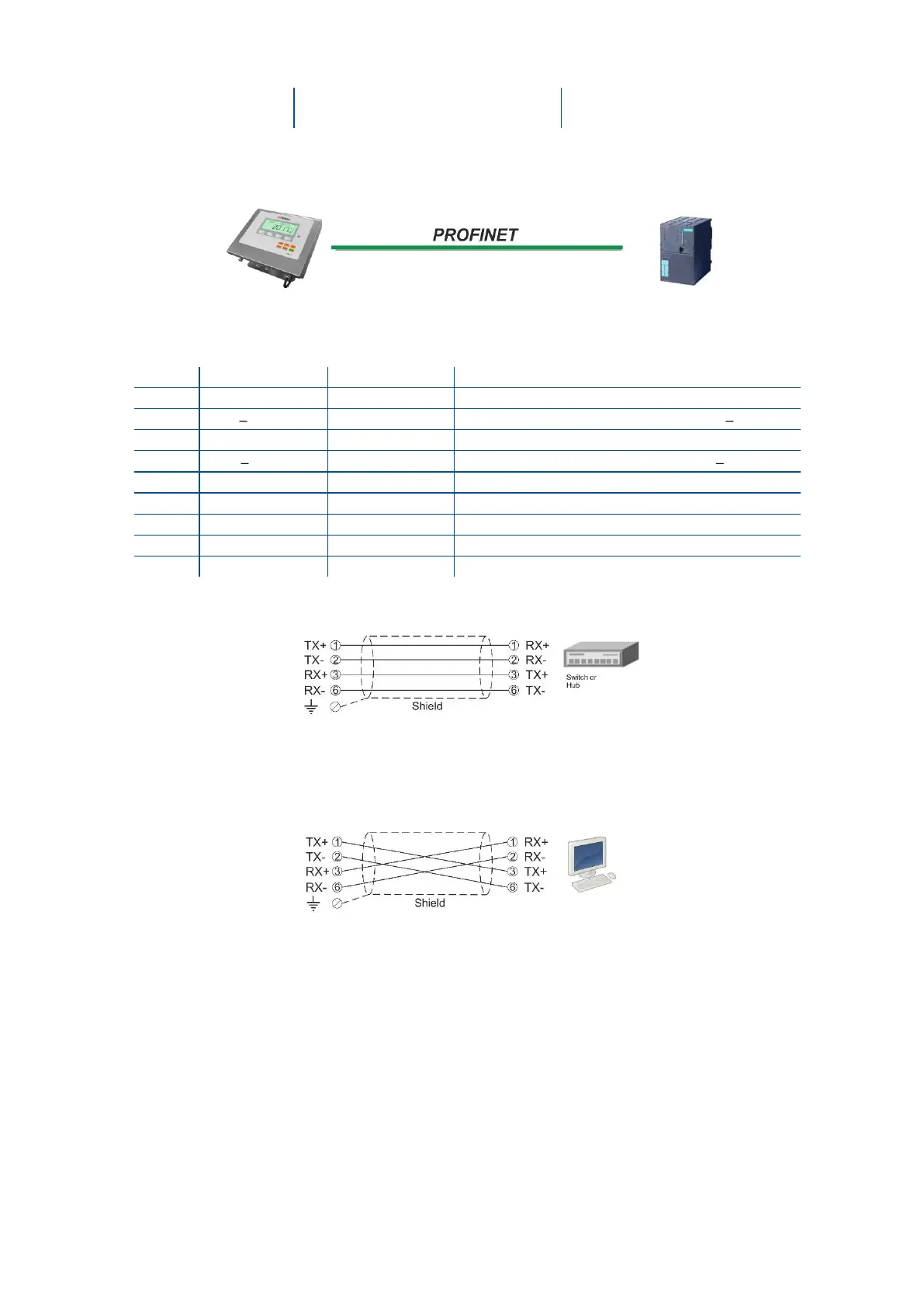
PROFINET Connector pin configuration (RJ45)
Differential Ethernet transmit data +
Differential Ethernet transmit data
Differential Ethernet receive data +
Differential Ethernet receive data
The HUB connection cabling will be a direct connection as shown below:
Figure 11.10 - HUB connection
The PC connection cabling will be done via cross cable as shown below. IP address blocks and gateway
address of weighing terminal and PC should be the same in cross connection.
Figure 11.11 - Cross PC connection
Pin configuration of digital input and output connector is described on page 76.
11.10.2 Data Format
Data format of weight value can be programmable for Floating point (IEEE 754) or Integer. Refer to
parameter [ 191 ].