FT-111, User Manual Rev. 2.0.0, June 2022 Page 15 of 137
4 INSTALLATION
PRECAUTION: Read this section carefully before installation of the instrument. Applying the
recommendations in this section will increase your system reliability and its long-term performance.
4.1 RECOMMENDATIONS
4.1.1 Environment
The weighing terminal should be placed in an area which is clean, not getting direct sun light if possible,
having a temperature between -15 ºC and +55 ºC and humidity not exceeding 80% non-condensing. All
external cables should be installed safely to avoid mechanical damages.
This instrument is very low-level signal measuring instrument. To avoid electrical noise, it should be
separated from equipment that produce electrical noise. The instrument body must be connected to the
good ground against the electromagnetic disturbances. Load cell cable must be separated from other cables
especially from power cables if possible. If there are electrical noise-generating equipment such as heavy
load switches, motor control equipment, inductive loads etc., please pay attention against the EMC
interference and take all the prevention. Connect parallel reverse diodes to the DC inductive loads like relays,
solenoids etc. to minimize voltage peaks on the DC power lines.
4.1.2 Mechanical Installation Recommendations
You may install your weighing indicator on a column, on a table or on a wall. Take care of the housing
drawings and dimensions given in this manual to design your weighing scale or weighing station
mechanically.
4.1.3 Cabling Recommendations
All cables coming to the instrument must be of high quality and shielded. Distance from load cell cables,
interface cables and DC power supply cables to power line cables must be minimum 50 cm. The separate
cable tray usage for these low signal level cables is strongly recommended.
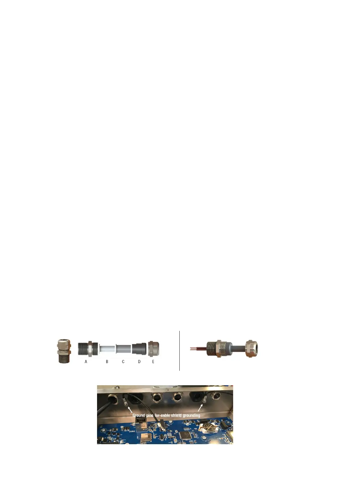
For cable connections of different thicknesses, as seen in Figure 4.1 there are 3 interlocking gaskets with
different diameters, indicated as B, C, and D, inside the glands used in the FT-111 weighing terminal.
Depending on the thickness of the cable, remove the gaskets B and C respectively, pass the cable through the
gland and tighten it. In this way, wires ranging in thickness from 4 to 8 mm can be easily connected to the
terminal using the same gland with the appropriate sealing combination.
To maintain the immunity of the device against electromagnetic interference, the cable shields should be
connected to the grounding pins inside the device, shown in Figure 4.2.