FT-111, User Manual Rev. 2.0.0, June 2022 Page 118 of 137
11.14.3 XDD Configuration
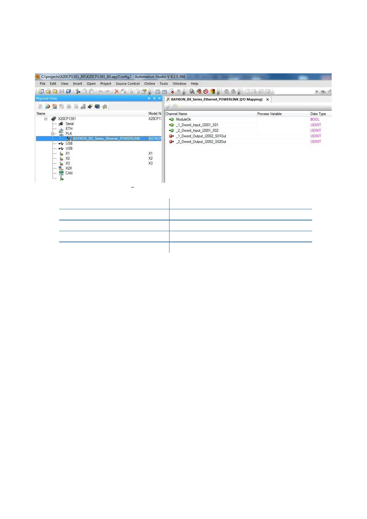
Powerlink data structures consist of 2 pcs Input-2 words and 2 pcs Output-2 words. XDD configuration for
PLC programmers is shown in Figure 11.26.
Figure 11.26 Configuration of module properties with XDD file
1
st
Dword ( FT-111 Output to PLC Input )
2
nd
Dword ( FT-111 Output to PLC Input )
1_Dword_Output_I2002_S01Out
1
st
Dword ( PLC Output to FT-111 Input )
2_Dword_Output_I2002_S02Out
2
nd
Dword ( PLC Output to FT-111 Input )
11.14.4 Powerlink Data Structure
For the Data Structure see Appendix 1, page 118