FT-111, User Manual Rev. 2.0.0, June 2022 Page 26 of 137
4.3 INSTALLATION OF OPTIONAL BOARDS
This section describes the mechanical installation of optional interface boards which are digital Input/ output,
analogue output, Profibus, Profinet, EtherNET/IP, EtherCAT, Powerlink, CC-Link, and CANopen. Follow the
steps below at installation of the interface option board.
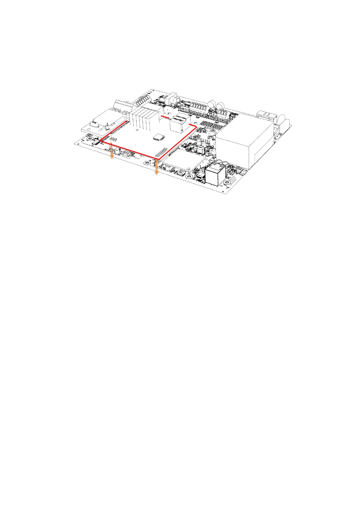
Figure 4.16 - The mechanical installation of optional board
1. De-energize the instrument, remove all the electrical connections, and carry it to the safe area.
Option board must be installed in a safe area. After de-energizing the instrument wait 30
seconds to open it.
2. Remove the M3x6 mm screw at M7 connection point.
3. Install 11 mm spacer which is supplied together with option board to the M7 connection point.
4. Install 7 mm spacers which are supplied together with option board to the M6 and M10
connection points.
5. Install the option board to the J5 and J3 connectors carefully.
6. Mount the M3 x 6 mm screw to fix option board to the spacer.
7. If you need additional gland, Install Ex-gland which is supplied together with option board to
instead of a blind plug.
8. Install cables to the option board as described in the related sections.