EasyManua.ls Logo

Flintec FT-111 - Appendix 1: Data Structure; Profibus, Profinet, EtherNET;IP, EtherCAT, CC-Link, Powerlink

Flintec FT-111
137 pages
Print Icon
To Next Page IconTo Next Page
To Previous Page IconTo Previous Page
Loading...
FT-111, User Manual Rev. 2.0.0, June 2022 Page 119 of 137
12 APPENDIX 1 DATA STRUCTURE PROFIBUS, PROFINET,
ETHERNET/IP, ETHERCAT, CC-LINK, POWERLINK
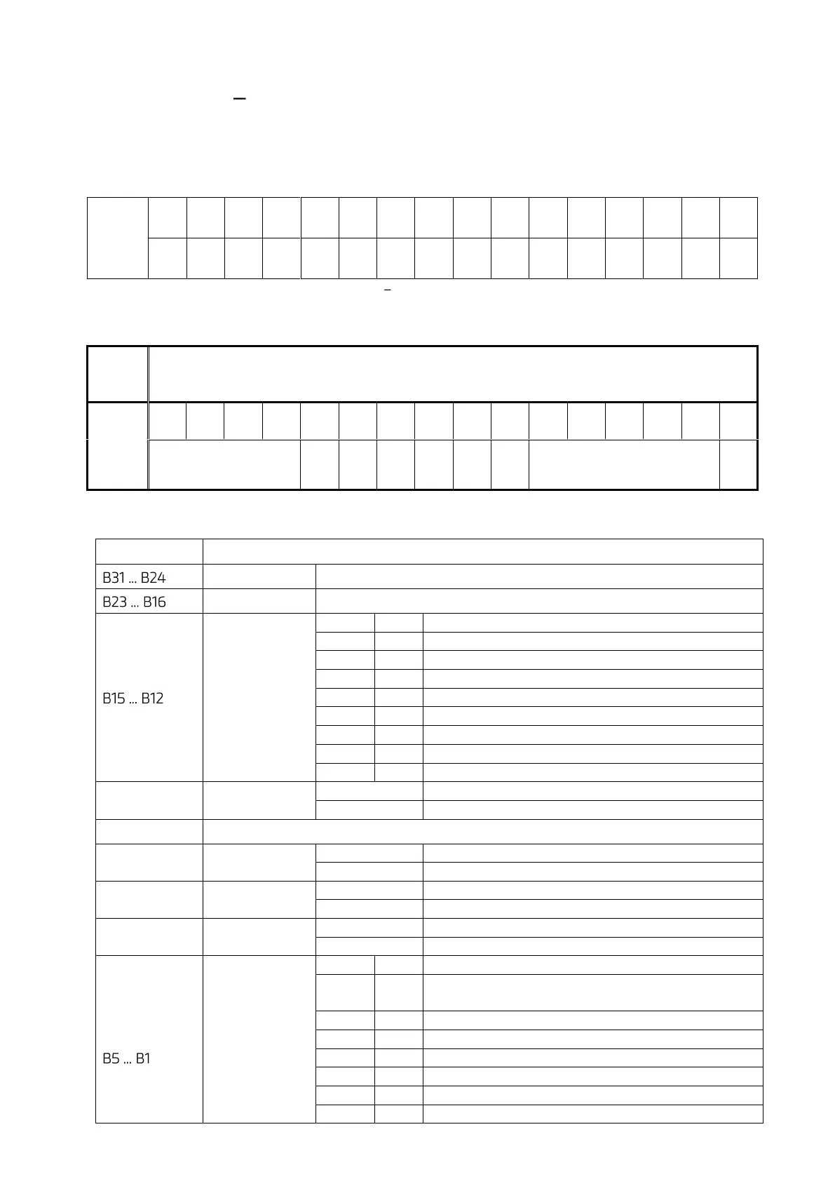
The write and read table are similarly structured and bitwise of a Dword descripted below
Dword
(Only
read)
B31
B30
B29
B28
B27
B26
B25
B24
B23
B22
B21
B20
B19
B18
B17
B16
B15
B14
B13
B12
B11
B10
B9
B8
B7
B6
B5
B4
B3
B2
B1
B0
Table 12-1 Bitwise of a Dword
FT-111 Output to PLC Input
1st
Dword
(INPUT)
By default, Actual weight value is represented.
To represent other weight or calibration status, refer to next Dword.
2nd
Dword
(INPUT)
Out
5
Out
4
Out
3
Out
2
Out
1
In
4
In
3
In
2
In
1
Error codes
FT-111
Unit
Centre
of
zero
Gross
Net
SD
Read command response
Cmd
Flg
Description of Input 2
nd
Dword (INPUT)
Bit Number
Description
Digital Outputs
Output bit status (Active = 1)
Digital Inputs
Input bit status (Active = 1)
Error Codes
of FT-111
Bin
Dec
Descriptions
0000
0
No error found
0001
1
ADC out
0010
2
ADC over
0011
3
ADC under
0100
4
System Error
0101
5
In programming mode
0110
6
Low/High Voltage Error
0111
7
Tilt Switch is active
B11
Unit
0
First unit
1
Second unit
B10-B9
Not used
B8
Centre of zero
0
Weight is out of zero range
1
Weight is in zero range
B7
Indication
0
Gross
1
Net
B6
Stability
Detection
0
Stable
1
Unstable
Read
Command
Response
Bin
Dec
Descriptions
0000
0
0
Actual weight (Net if the indication is in Net)
00001
1
Gross weight
00010
2
Tare weight
00011
3
ALL Status ( Refer to Table 12-2 )
00100
4
Calibration Status ( Refer to
Table 12-3
)
00101
5
Last print value
00110
6
Not used

Table of Contents

Related product manuals