FT-111, User Manual Rev. 2.0.0, June 2022 Page 23 of 137
Pin number
(Terminal J13)
Differential Ethernet transmit data +
Differential Ethernet transmit data
Differential Ethernet receive data +
Differential Ethernet receive data
Metal body of the RJ45 connector
Table 4-7 Pin configuration of RJ45 Ethernet connector
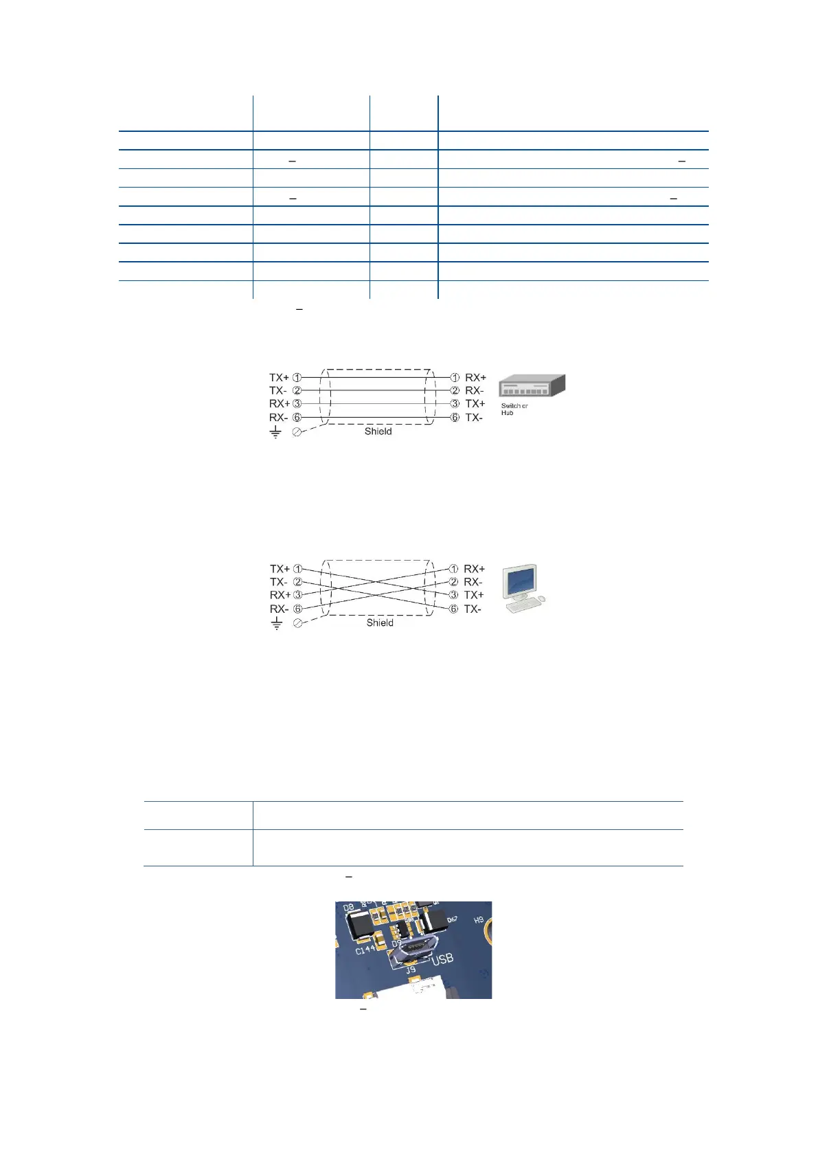
The HUB connection cabling is a direct connection as shown below:
Figure 4.12 - HUB connection
The PC connection cabling is done via a cross cable as shown below. IP address blocks and gateway address
of FT-111 and PC should be the same in cross connection.
Figure 4.13 - PC connection with cross cable
Important note:
Disconnect IndFace2x software before Ethernet interfacing.
Step 8: USB Port
The usage of the on-board USB 2.0 and its specifications are shown in the Table 4-8. You need the mini-USB
cable to connect the weighing terminal to the peripheral instrument. Refer to page 49 for USB port
configuration.
Interfacing with PC via USB 2.0
Continuous, Fast Continuous, BSI Protocol to PC near the
instrument.
Table 4-8 Data formats of the USB port
Figure 4.14 Micro USB port connector