FT-111, User Manual Rev. 2.0.0, June 2022 Page 117 of 137
In the case of LED warning, check cabling, configuration, IP address and device name. Power off the
instrument and reenergize the instrument 30 seconds later.
C, E LINK/Activity LED
11.14.1 Electrical Connection
Figure 11.24 - PLC Connection
Powerlink Connector pin configuration (RJ45)
Differential Ethernet transmit data +
Differential Ethernet transmit data
Differential Ethernet receive data +
Differential Ethernet receive data
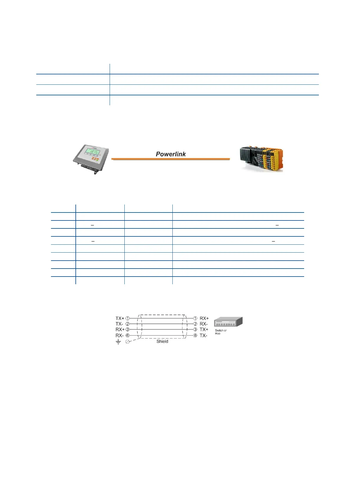
The HUB connection cabling will be a direct connection as shown below:
Figure 11.25 - HUB connection
Pin configuration of digital input and output connector is described on page 76.
11.14.2 Data Format
Data format of weight value can be programmable for Floating point (IEEE 754) or Integer. Refer to
parameter [ 191 ].