EasyManua.ls Logo

Flintec FT-111 - Data Format; CC-Link Configuration; 4 CC-Link Data Structure

Flintec FT-111
137 pages
Print Icon
To Next Page IconTo Next Page
To Previous Page IconTo Previous Page
Loading...
FT-111, User Manual Rev. 2.0.0, June 2022 Page 115 of 137
Pin configuration of digital input and output connector is described in Appendix 3, page 76.
11.13.2 Data Format
Data format of weight value can be programmable for Floating point (IEEE 754) or Integer. Refer to
parameter [ 191 ].
11.13.3 CC-Link Configuration
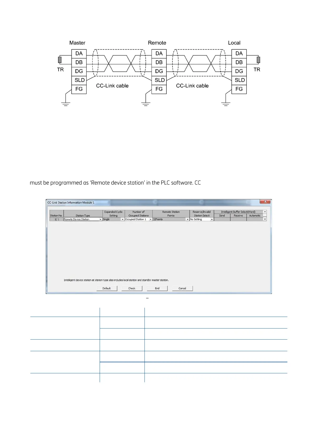
Weighing terminal has occupied one station area on CC-Link network and station type of weighing terminal
-Link configuration for PLC
programmers is shown in Figure 11.23.
Figure 11.23 Station information
Input/Output
Definition
Description
Remote Register (RWr)
RWr0, RWr1
1
st
Dword Input (
FT-111 Output to PLC Input
)
RWr2, RWr3
2
nd
Dword Input (
FT-111 Output to PLC Input
)
Remote Input (RX)
RX0 ~ RX31
Not used
Remote Register (RWw)
RWw0, RWw1
1
st
Dword Output (
PLC Output to FT-111 Input
)
RWw2, RWw3
2
nd
Dword Output (
PLC Output to FT-111 Input
)
Remote Output (RY)
RY0 ~ RY31
Not used
11.13.4 CC-Link Data Structure
For the Data Structure see Appendix 1, page 118

Table of Contents

Related product manuals