FT-111, User Manual Rev. 2.0.0, June 2022 Page 24 of 137
Step 9: Alibi Memory (option
If you install the alibi memory to the main board, order Alibi memory SD card from Flintec or dealer. The alibi
memory SD card should be inserted into the SD1 card slot which is between load cell terminal and metal box
of the analogue digital converter. Refer to page 77.
Step 10: Optional Board Installation
FT-111 has a free port to add digital inputs and outputs and fieldbus interfacing features to the instrument.
You will find all data to install the optional peripheral on page 26.
Step 11: Power Source Connection and Grounding
The weighing instrument measures very low signal levels. The quality of the power line and grounding will
determine the accuracy and the safety of your measuring system. The instrument should not share power
lines with noise-generating parts such as heavy load switching relays, motor control equipment, inductive
loads, etc. If the condition of the power supply in the plant is poor, prepare a special power line and
grounding. Before connecting the power source check its voltage and be sure that it is the same with the
voltage written on the weighing terminal.
Table 4-9 Pin configuration of power supply connector
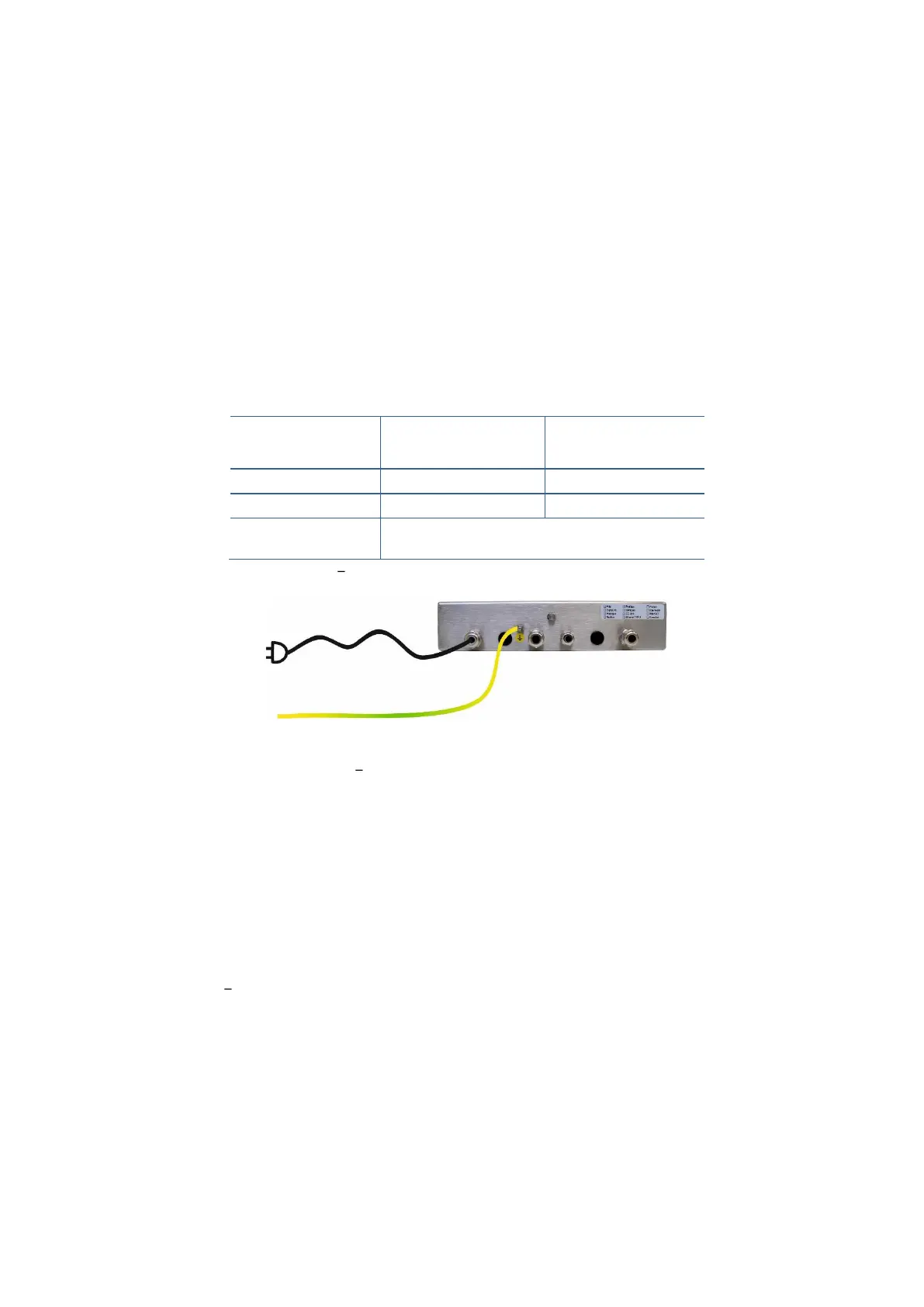
Figure 4.15 Power source connection and grounding
If the voltage is correct:
1. Connect the grounding wire to the grounding screw near glands on the housing of the
instrument.
2. Connect grounding points of other instruments in the system to the FT-111 grounding screw in
Figure 4.15 or directly to the system grounding point.
Warning:
The instrument should be shielded. Connect the shield to the protective earth with a cable having a
minimum of 4 mm
2
cross section.
3. The 90 240 VAC supplied instruments are shipped with power cord. Prepare the power outlet
for the instrument.
4. The 24 VDC supplied instruments are shipped with installed 2 meters power supply cable.
Connect this cable to power supply as shown in Table 4-9
5. Energize the instrument after checking all electrical and grounding connections.
In case the power source is not proper, do not connect the scale to the power source and contact your
authorized dealer.