EasyManua.ls Logo

Flintec FT-111 - ESI Configuration; Ethercat Data Structure

Flintec FT-111
137 pages
Print Icon
To Next Page IconTo Next Page
To Previous Page IconTo Previous Page
Loading...
FT-111, User Manual Rev. 2.0.0, June 2022 Page 113 of 137
11.12.3 ESI Configuration
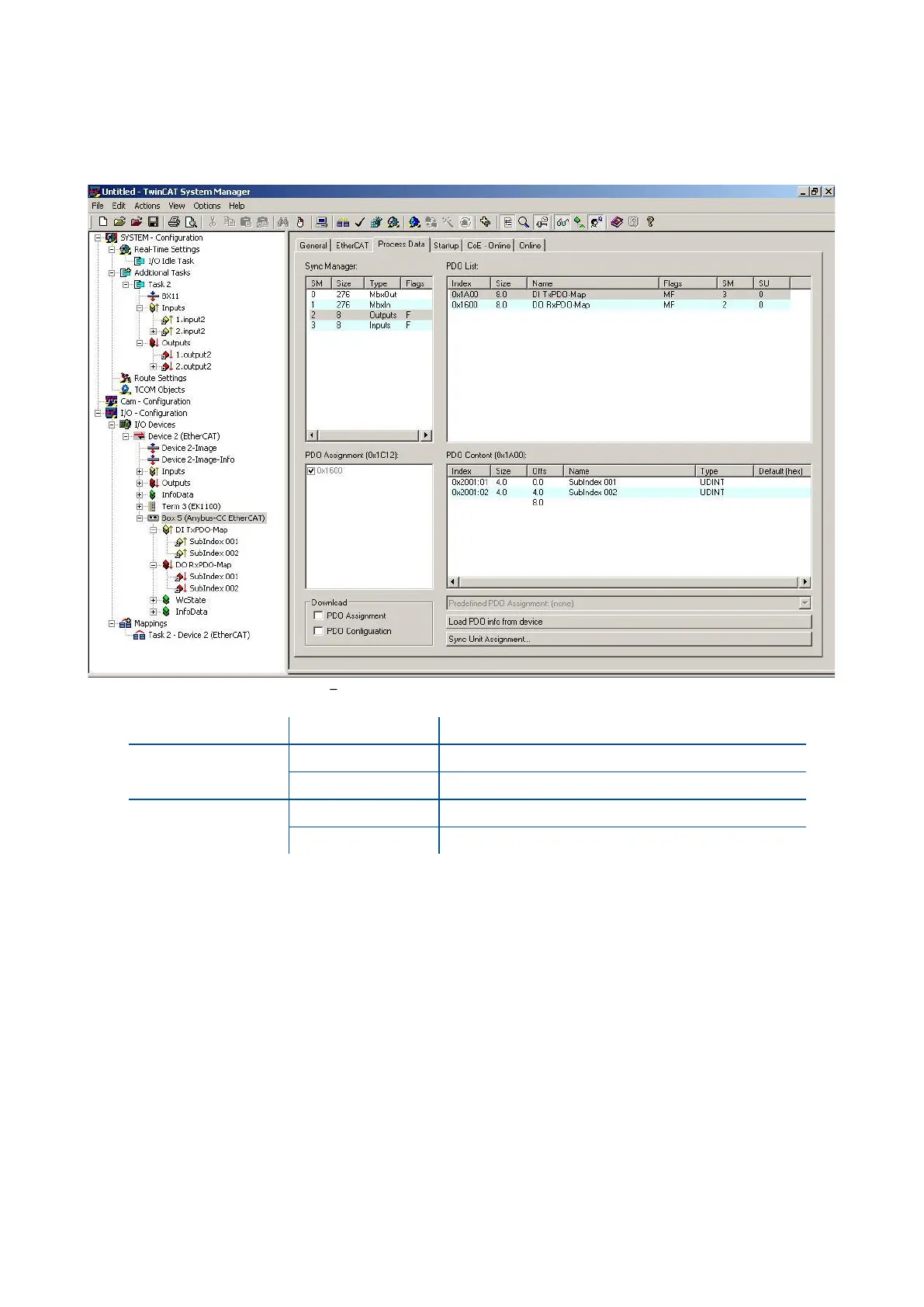
EtherCAT data structures consist of 2 pcs Input-2 words and 2 pcs Output-2 words. ESI configuration for PLC
programmers is shown in Figure 11.21.
Figure 11.21 Configuration of module properties for Beckhoff
Input/Output
Definition
Description
DI TxPDO-Map
SubIndex 001
1
st
Dword (
FT-111 Output to PLC Input
)
SubIndex 002
2
nd
Dword (
FT-111 Output to PLC Input
)
DO RxPDO-Map
SubIndex 001
1
st
Dword (
PLC Output to FT-111 Input
)
SubIndex 002
2
nd
Dword (
PLC Output to FT-111 Input
)
11.12.4 EtherCAT Data Structure
For the Data Structure see Appendix 1, page 118

Table of Contents

Related product manuals