Issue/Rev. 0.2 (12/12)
Page 78 • MN0M023
7 Block OUTPUTS Device Functions Proline Promass 83
VALUE F HIGH
(continued)
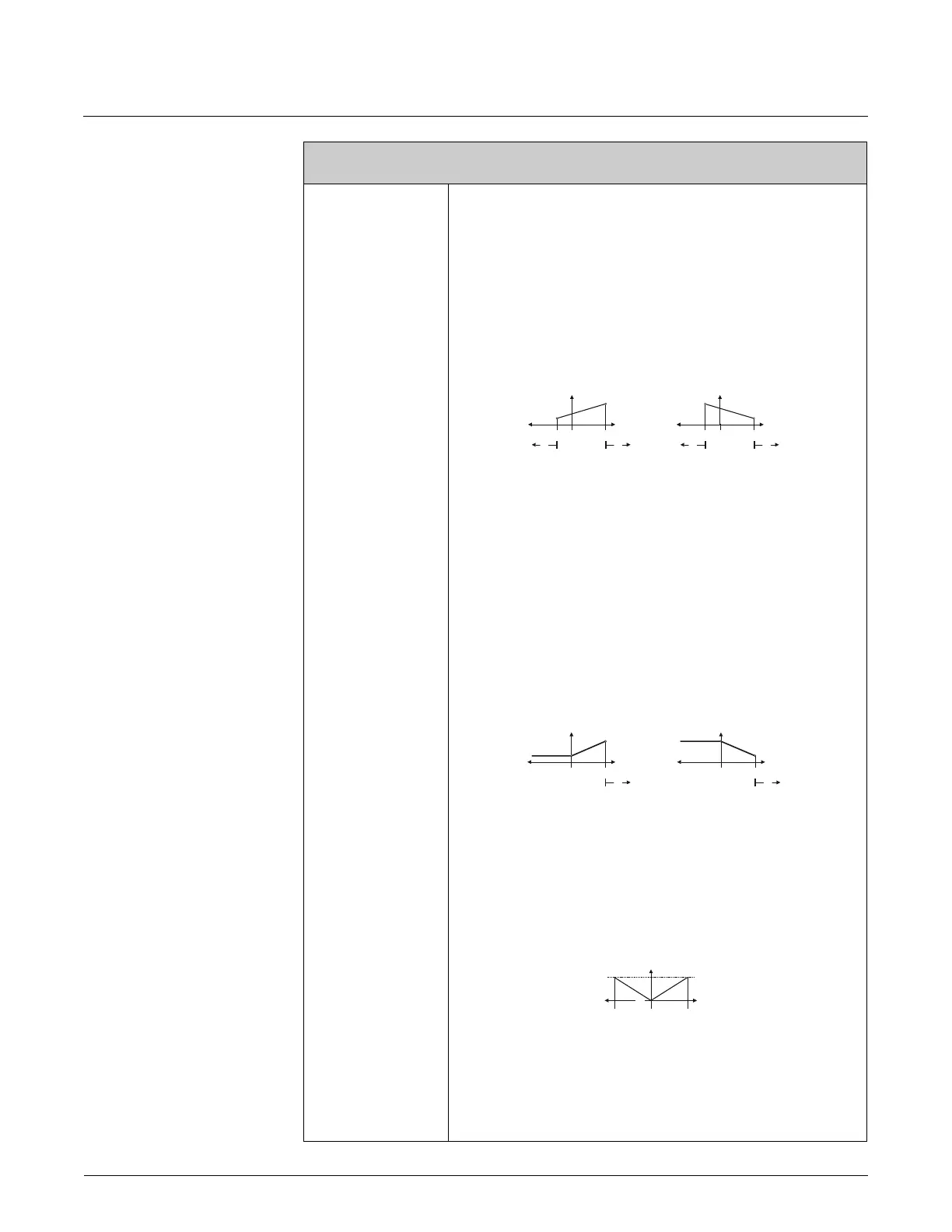
Parameter setting example 1:
1. VALUE F LOW (4204) = not equal to zero flow (e.g. –5 kg/h)
VALUE F HIGH (4205) = not equal to zero flow (e.g. 10 kg/h) or
2. VALUE F LOW (4204) = not equal to zero flow (e.g. 100 kg/h)
VALUE F HIGH (4205) = not equal to zero flow (e.g. –40 kg/h)
and
MEASURING MODE (4004) = STANDARD
When you enter the values for VALUE F LOW and VALUE F HIGH the working range of
the measuring device is defined. If the effective flow drops below or exceeds this working
range (see Fig. m), a fault/notice message is generated (#355-358, frequency area) and
the frequency output responds in accordance with the parameters set in the function
FAILSAFE MODE (4209).
A0001276
Parameter setting example 2:
1. VALUE F LOW (4204) = not equal to zero flow (e.g. 0 kg/h)
VALUE F HIGH (4205) = not equal to zero flow (e.g. 10 kg/h) or
2. VALUE F LOW (4204) = not equal to zero flow (e.g. 100 kg/h)
VALUE F HIGH (4205) = not equal to zero flow (e.g. 0 kg/h)
and
MEASURING MODE (4004) = STANDARD
When you enter the values for VALUE F LOW and VALUE F HIGH the working range of
the measuring device is defined. In doing so, one of the two values is configured as zero
flow (e.g. 0 kg/h).
If the effective flow drops below or exceeds the value configured as the zero flow, no
fault/notice message is generated and the frequency output retains its value.
If the effective flow drops below or exceeds the other value, a fault/notice message is
generated (#355-358, frequency area) and the frequency output responds in accordance
with the parameters set in the function FAILSAFE MODE (4209).
A0001277
Deliberately only one flow direction is output with this setting and flow values in the
other flow direction are suppressed.
Parameter setting example 3:
MEASURING MODE (4206) = SYMMETRY
The frequency output signal is independent of the direction of flow (absolute amount of
the measured variable). The VALUE F LOW m and VALUE F HIGH n must have the
same sign (+ or
-). The “VALUE F HIGH” o (e.g. backflow) corresponds to the mirrored
VALUE F HIGH n (e.g. flow).
A0001278
ASSIGN RELAY (4700) = FLOW DIRECTION
With this setting e.g. the flow direction output via a switching contact can be made.
Parameter setting example 4:
MEASURING MODE (4004) = PULSATING FLOWopage 68 ff.
Function description
OUTPUTS o PULSE/FREQUENCY OUTPUT (1...2) o CONFIGURATION (FREQUENCY)
-5 0 0
-40
0
0
125 125
10 100
Hz Hz
mm
33
/h /h
➀➀➀➀
00
0
0
125
125
10 100
Hz Hz
mm
33
/h /h
➀➀
Q
125
Hz
0
➀➁➂