Issue/Rev. 0.2 (12/12)
Page 88 • MN0M023
7 Block OUTPUTS Device Functions Proline Promass 83
OUTPUT SIGNAL
(4226)
! Note!
Function is not available unless the PULSE setting was selected in the OPERATION
MODE (4200) function.
For selecting the output configuration of the pulse output.
Options:
0 = PASSIVE - POSITIVE
1 = PASSIVE - NEGATIVE
2 = ACTIVE - POSITIVE
3 = ACTIVE - NEGATIVE
Factory setting: PASSIVE - POSITIVE
Explanation
• PASSIVE = power is supplied to the pulse output by means of an external power
supply.
• ACTIVE = power is supplied to the pulse output by means of the device-internal
power supply.
Configuring the output signal level (POSITIVE or NEGATIVE) determines the quiescent
behavior (at zero flow) of the pulse output.
The internal transistor is activated as follows:
• If POSITIVE is selected, the internal transistor is activated with a positive signal level.
• If NEGATIVE is selected, the internal transistor is activated with a negative signal
level (0 V).
! Note!
With the passive output configuration, the output signal levels of the pulse output depend
on the external circuit (see examples).
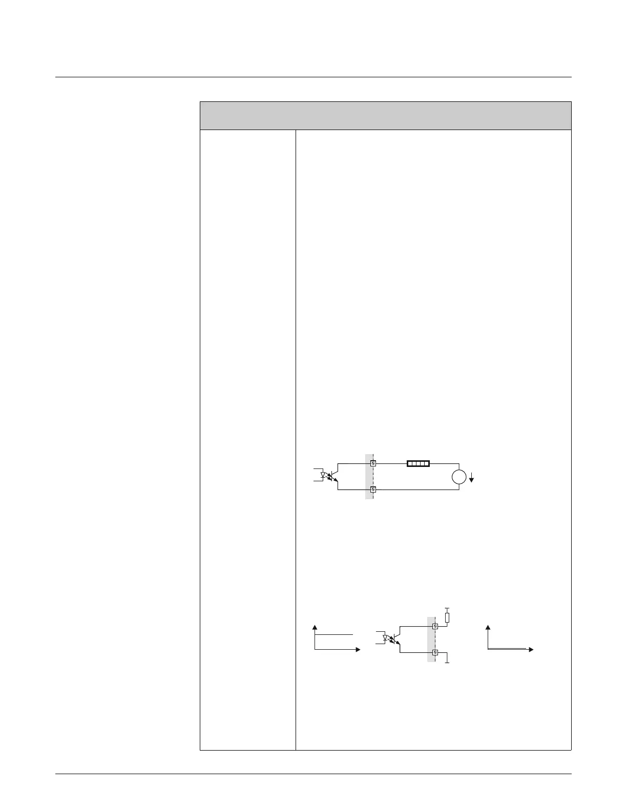
Example for passive output circuit (PASSIVE)
If PASSIVE is selected, the pulse output is configured as an open collector.
A0001225
m = Open collector
n = External power supply
! Note!
For continuous currents up to 25 mA (I
max
= 250 mA / 20 ms).
Example for output configuration PASSIVE-POSITIVE:
Output configuration with an external pull-up resistance.
In the quiescent state (at zero flow), the output signal level at the terminals is 0 V.
A0004687
m = Open collector
n = Pull-Up-Resistance
o = Transistor activation in “POSITIVE” quiescent state (at zero flow)
p = Output signal level in quiescent state (at zero flow)
Function description
OUTPUTS o PULSE/FREQUENCY OUTPUT (1...2) o CONFIGURATION (PULSE)
1
5
8 3
7
+
-
=
U =30VDC
max
m
n
U =30VDC
max
+
U (V)
t
U (V)
t
o
p
m
n
(continued on next page)